
Conformal Coating Dipping: Process Controls
Dip speed, dwell time, viscosity control and film build consistency
Dip coating can be a highly efficient conformal coating method, but stable results come from process control rather than immersion alone. Film thickness, drainage behaviour, air entrapment risk and repeatability are all shaped by how viscosity, immersion profile, withdrawal speed, dwell time and bath condition are managed.
This article focuses on the control variables that make dip coating repeatable in production. It is intended to sit alongside the practical step-by-step guide to dip coating a PCB and the wider process model for dip coating behaviour and stability.
Used well, dip coating can deliver reliable wrap-around coverage with low waste and strong repeatability. Used badly, it can create unstable film build, retained coating, air bleed-out, edge pooling and inconsistent performance between lots, shifts or products.
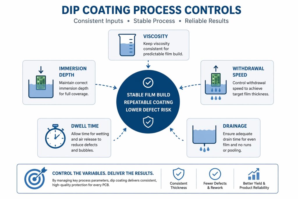
Stable dip coating depends on controlling viscosity, immersion, withdrawal speed, dwell time and drainage — not a single parameter.
Why process controls matter in dip coating
Dipping immerses the assembly into a coating bath and can provide full coverage over complex 3D geometry and beneath many component forms. However, good coverage alone is not the same as good process control. The important question is whether the coating is being applied within a stable and repeatable window.
That stability depends on controlling the interaction between material condition, machine motion, drainage behaviour and product geometry. If those variables drift, the process can become inconsistent even when the same coating chemistry is being used.
Controlling coating thickness
Film build in dip coating is shaped primarily by viscosity, withdrawal speed, immersion profile, drainage behaviour and local geometry. Although these are often discussed separately, they should be treated as an interacting set rather than as isolated adjustments.
- Withdrawal speed: this is one of the main controls on wet film build. It should be validated against the target thickness on representative assemblies, not only on flat coupons.
- Viscosity: stable viscosity supports predictable coating thickness and drainage. If viscosity drifts, film build and local accumulation can drift with it.
- Dwell and drainage: dwell affects wetting, while drainage affects the final distribution of the liquid after withdrawal.
- Geometry: sharp edges, lower features, gaps and dense component layouts all change how the local film behaves.
A commonly quoted example might be an acrylic at around 200 cP with a withdrawal speed near 150 mm/min producing a film in the 25–50 µm range, but this should always be treated as illustrative only. Actual thickness must be verified against the real coating, real assembly and real process window. For practical measurement methods, see how coating thickness is verified in production.
Immersion profile, dwell time and air entrapment
Entry into the coating bath matters just as much as withdrawal. If the assembly is immersed too quickly, air can become trapped around leads, beneath components and within restricted geometries. That trapped air may then bleed out during dwell, withdrawal or drainage, causing bubbles, voids or frog-eye type defects.
Dwell time should be long enough to allow proper wetting, but not treated as a substitute for good immersion control. A poorly controlled entry profile can create instability before the board has even been withdrawn from the bath.
- Immersion speed: too fast can promote air entrapment.
- Dwell time: supports wetting but must be defined and repeatable.
- Geometry awareness: tight gaps, underside features and leaded areas are higher-risk zones.
This is one reason process validation should include inspection for bubbles and local disruption around difficult features, not only bulk film thickness.
Horizontal dipping and orientation control
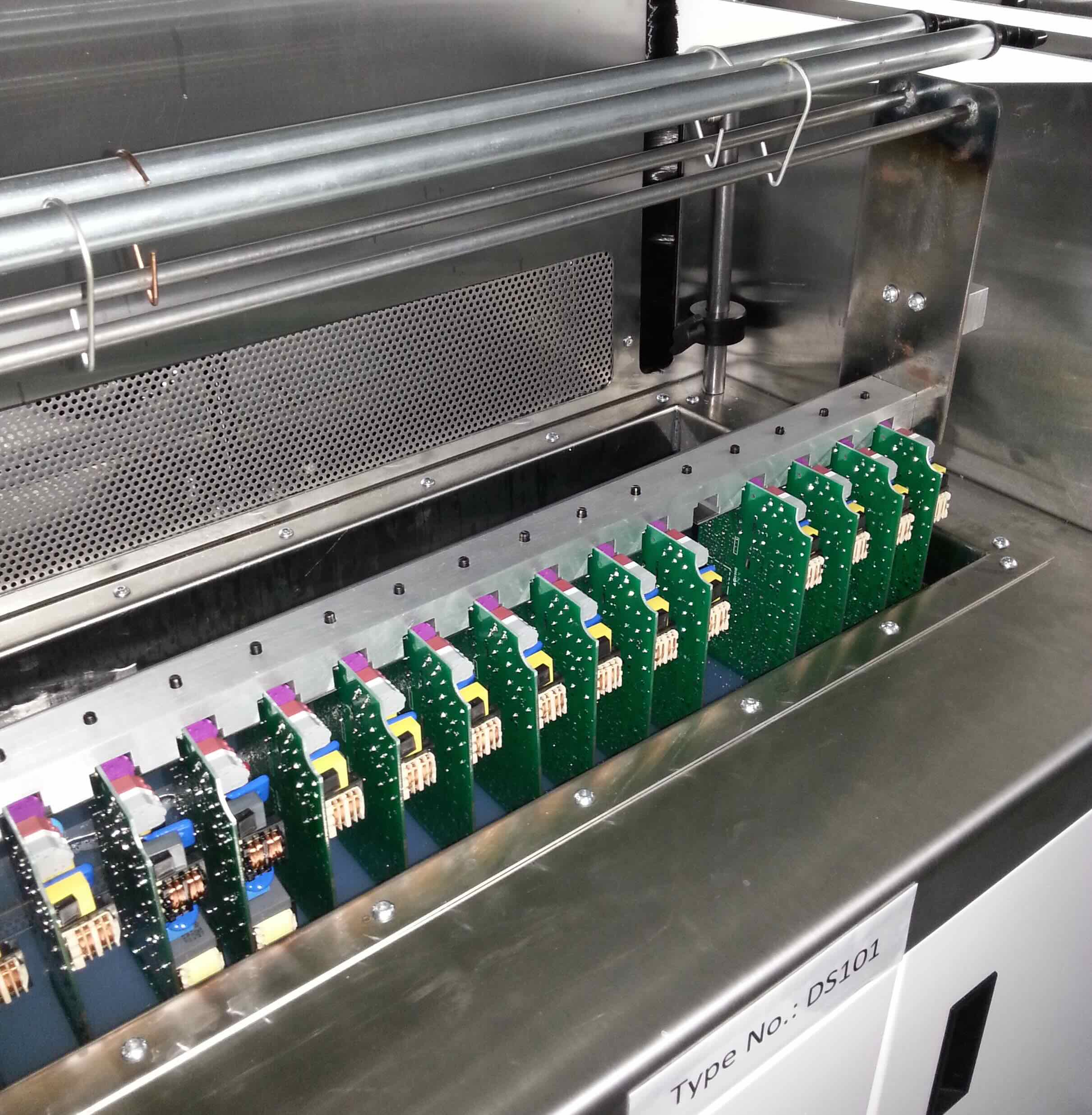
Some assemblies can be processed using horizontal dipping with systems such as the DS101 Dip Coating System or custom inline dip coating systems. However, horizontal dipping demands close control of drainage, masking and part orientation.
Orientation influences how coating collects, drains and moves into restricted spaces. Where the process is not matched to the assembly geometry, local pooling, retained coating and edge accumulation can appear even if the global process settings appear reasonable.
Horizontal dipping should therefore be viewed as a controlled process choice, not simply a mechanical handling option.
Dip coating repeatability depends on controlling the bath, the motion profile and the drainage behaviour — not just the coating itself.
Monitoring and controlling viscosity
Most batch dip systems rely on a viscosity cup to monitor flow time and confirm the bath remains within the validated process window. This is often the most practical approach, but it only works if checks are performed consistently and interpreted correctly against temperature and process history.
In higher-control systems, inline viscosity measurement and automatic correction can be used to add thinner or fresh coating in order to maintain film build more consistently across the shift. This is especially useful where solvent loss, bath age or long production runs would otherwise cause measurable drift.
Good viscosity control is not just about adding thinner. It is about maintaining a known process window while understanding what is changing in the bath over time.
Dip tank height control
Stable dip level is another important control variable. Systems such as the DS101 dip machine manage coating height through a weir edge so that excess material flows into a sump. This helps stabilise dip level and reduces the effect of material loss, solvent evaporation and contamination build-up.
If liquid level drifts, the assembly may experience different immersion geometry, different drainage paths and different local wetting conditions. In other words, tank height control is part of process consistency, not just housekeeping.
Automated process controls
Automation can improve repeatability by reducing operator-driven variation and keeping the bath within a tighter control window.
- Automated dosing: sensors detect low level and feed material from sealed containers to maintain coating height.
- Material top-up systems: reduce the risk of the tank running dry and limit interruptions to production.
- Material heating: holding coatings at a stable temperature, often around 20–30 °C depending on the chemistry, can improve viscosity stability and reduce bubble formation during withdrawal.
- Closed-loop viscosity control: inline systems can automatically correct viscosity drift within the defined operating range.
These controls are most useful where repeatability matters more than operator intuition, such as longer runs, tighter thickness windows or more difficult assembly geometries.
Advanced options for bath stability and repeatability
- Argon or dry-air blanket: reduces solvent evaporation and can help protect moisture-sensitive coatings from ambient humidity.
- Filtration baskets: capture debris and cured particles before they reach the pump or recirculation system, helping extend material life.
- Custom board fixtures: maintain immersion depth, alignment and drainage in a more repeatable way across different PCB designs.
These options are not always necessary, but they become increasingly valuable when the process window is narrow or when contamination, drift or geometry variation has already shown itself to be a risk.
Best practices for dip coating control
- Record tank hours, board volume, solvent additions and viscosity checks so drift can be tracked rather than guessed.
- Inspect and protect the bath if lids remain open for long periods, as contamination and evaporation will change process behaviour.
- Match the process window to the coating chemistry, whether acrylic, silicone, urethane or water-based.
- Use witness boards or representative coupons as part of validation, but do not assume they fully represent the most difficult product geometry.
- Inspect under-component zones and local build areas, not only the most visible surfaces.
For the wider process model behind these controls, see dip coating process behaviour, film formation and stability. For validation structures, see how witness boards and test coupons support coating validation. For a broader view of how process drift turns into failure, see why conformal coating fails on complex PCB assemblies.
Related articles and next reading
- Dip Coating Process Control: From Fluid Behaviour to Production Stability – the wider process model behind film formation, drainage and stability
- How to Dip Coat a PCB – practical step-by-step dip coating guidance
- Conformal Coating Viscosity – Importance in Process Control – measurement and control of bath behaviour
- Thickness Verification Methods – measurement and control of coating thickness
- Conformal Coating Test Coupons & Witness Boards – validation using representative structures
- Why Conformal Coating Fails on Complex PCB Assemblies – why instability shows up more readily on difficult assemblies
- Pinholes, Bubbles and Foam – air entrapment and bubble-related defects
- Capillary Flow and Wicking – fluid movement into unwanted areas
Why Choose SCH Services?
SCH Services supports dip coating process development, equipment selection, subcontract coating services and operator training with practical engineering input based on real production constraints.
- Conformal Coating Services: Production coating, trials and process support
- Training: Practical conformal coating training for operators and engineers
- Equipment: DS101 Dip Coating System and custom inline dip coating systems
Where appropriate, SCH can help define whether a dip process is robust enough for the required coating chemistry, assembly design and production outcome.
Disclaimer:
This article is provided as general technical guidance only. Final process settings, equipment selection, safety controls and production suitability should always be confirmed through appropriate engineering trials, validation work and applicable customer or industry standards.
