
Conformal Coating Thickness Passes but Coverage Still Fails
Why acceptable thickness measurements do not always prove effective protection
Bulletin category: Inspection & Verification | Topic: Coating thickness, coverage, continuity and inspection risk
A conformal coating thickness reading can pass while the assembly still contains coverage gaps, weak edges, shadowed areas or unprotected features.
Thickness measurement confirms film build at the measurement point. It does not automatically prove that coating coverage is continuous across the whole PCB assembly.
The practical risk is that engineers may accept a coating process because the measured thickness is within range, even though the coating is not protecting the areas that matter most.
A PCB assembly can pass coating thickness verification while still containing coverage gaps, shadowed areas or poorly protected features that increase reliability risk.
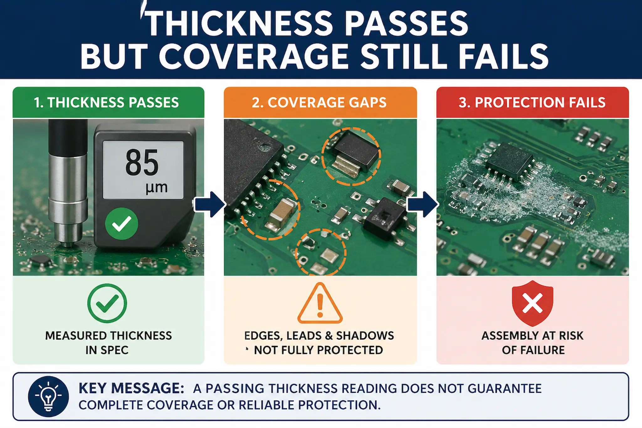
The inspection gap
Thickness passes
The measured point is within the required coating thickness range.
Coverage varies
Edges, tall components, shadowed areas or keep-out boundaries may still be weak.
Protection fails
The assembly can remain vulnerable despite a passing thickness result.
Simple inspection view: thickness at one point does not prove complete coating protection.
What engineers usually see
This problem often appears when inspection evidence looks acceptable but performance, reliability or detailed review shows the coating is not doing what the process assumed.
- Thickness readings pass at selected measurement points.
- UV trace appears present across much of the assembly.
- Edges, leads or vertical surfaces remain thin or poorly protected.
- Shadowed areas behind tall components receive less coating.
- Pooling or heavy build exists in one area while another area is marginal.
- Failures appear later despite apparently acceptable inspection records.
A common warning sign is when the inspection record says the board passed, but the failure location was never part of the measurement or inspection focus.
Common hidden causes
Thickness and coverage are related, but they are not the same control point. A good thickness value can still hide local protection risks.
- Measurement location bias: readings are taken where access is easy rather than where coating risk is highest.
- PCB geometry: tall parts, edges, leads, connectors and shadowed areas affect local coating coverage.
- Drainage and pooling: liquid coating can collect in some areas while draining away from others.
- Spray or dip dynamics: application method, orientation, withdrawal rate, spray angle and pass overlap affect coverage.
- UV interpretation: fluorescence can show coating presence without proving thickness, continuity or protection.
- Hidden contamination: a board can look clean and still contain residues or surface-condition problems that affect coating wetting and continuity. See Boards Look Clean but Still Fail Conformal Coating.
- Specification misunderstanding: a thickness range may be treated as proof of protection without defining where it must be achieved.
Process reality: Thickness verification proves only what was measured, where it was measured and under the limits defined for that location.
This is why thickness verification must be linked to coating coverage, inspection zones and assembly risk rather than treated as a standalone pass/fail result.
Recommended shop-floor action
The aim is to confirm whether the thickness measurement genuinely represents the areas that need protection.
- Define critical coverage areas before coating and inspection begin.
- Measure thickness at representative and high-risk locations, not only convenient flat areas.
- Check edges, leads, component bodies, vertical surfaces and shadowed areas separately.
- Use UV inspection as a coverage aid, not as proof of coating protection.
- Compare thickness results with visual inspection, defect history and field-failure locations.
- Review whether the process creates both heavy-build and thin-build areas on the same assembly.
- Escalate recurring coverage gaps into process review rather than accepting a passing measurement point.
A useful practical check is to ask: does the thickness reading represent the risk area, or only the easiest place to measure?
Key message for engineers
Key message: A passing thickness reading does not prove full coating coverage unless the measurement plan reflects the real assembly risk.
Thickness verification is essential, but it must be used correctly. If the measurement location is not representative, the result may create false confidence.
The next action is to review the measurement plan, inspection locations, coating coverage expectations and assembly geometry together. If the process cannot consistently protect the required areas, the application method or coating strategy may need to be changed.
Related guidance
Why Choose SCH Services?
SCH Services supports coating inspection and process review by combining practical coating production experience with thickness verification, coverage assessment, failure investigation and operator training.
- Support with coating thickness plans, measurement locations and inspection interpretation.
- Practical experience with complex PCB assemblies, coating coverage limitations and process variation.
- Process-led guidance for improving coating reliability before inspection records create false confidence.
For recurring coating coverage concerns, SCH can help review whether the inspection plan, coating method and assembly design are producing genuine protection rather than only passing measurement points.
This bulletin is general technical guidance only. Final coating thickness limits, inspection locations, coating coverage requirements, process controls and acceptance criteria should be validated against the specific assembly, coating material, customer specification, production method and applicable qualification or reliability testing.
