
Why One Conformal Coating Thickness Reading Can Be Misleading
A practical engineering bulletin on local film build, PCB geometry and inspection risk
Bulletin Category: Process Control | Typical Environments: Manual spray, selective spray, dip coating, large PCB assemblies and thickness-controlled coating processes.
Conformal coating thickness rarely remains perfectly uniform across large or complex PCB assemblies. Even when the coating process is stable, local geometry, board orientation, component height and coating flow can all affect the final dry film build.
It is not unusual to see a PCB assembly pass thickness verification at one measurement location while thinner or heavier coating exists elsewhere on the same board.
This bulletin explains why one coating thickness reading should not be treated as proof of uniform coating coverage across the whole assembly.
Coating thickness can vary significantly across the same PCB assembly. One measurement location may not represent the entire board.
The common mistake
Many inspections rely on one or two convenient measurement locations. The problem is that coating thickness can vary significantly across the same assembly.
A compliant reading at one location does not automatically confirm compliant thickness elsewhere, especially on dense boards, tall components, connector areas, board edges or drainage points.
Process note: Thickness verification should confirm a controlled coating process, not just a convenient measurement result.
What engineers commonly find
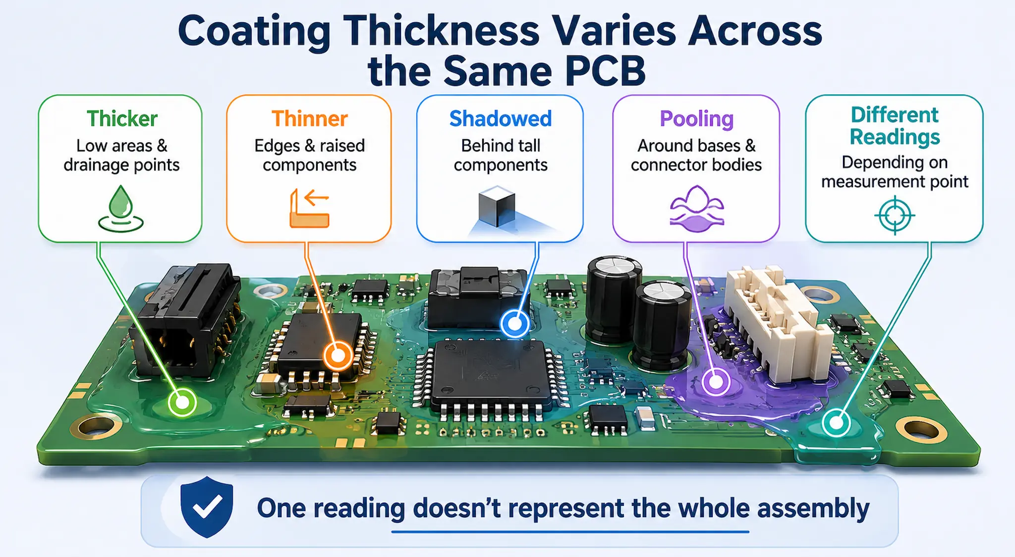
Thickness variation normally appears as local differences rather than a uniform high or low coating condition across the whole board.
- Thicker coating around low areas, edges, corners or drainage points.
- Thinner coating on sharp edges, raised component bodies or vertical surfaces.
- Pooling around component bases or connector bodies.
- Reduced coating build in shadowed areas or behind tall components.
- Different readings depending on where thickness is measured.
- Acceptable average thickness but questionable local coverage.
Key point: A single coating thickness reading may not represent the whole assembly, especially on large, dense or uneven PCB designs.
Inspection warning: Even where measured coating thickness is within specification, critical areas can still receive inadequate protection if coverage is incomplete, shadowed or interrupted by assembly geometry. For a practical example, see the bulletin Coating Thickness Passes but Coverage Still Fails.
Common hidden causes
Thickness variation is usually caused by a combination of process settings, board geometry and coating behaviour.
Board geometry
Large boards, tall components and uneven layouts affect coating flow, access and drainage.
Application method
Spray angle, spray distance, dip speed, withdrawal rate and pass overlap influence film build.
Drainage behaviour
Liquid coating can collect in low areas or drain away from vertical and edge features.
Material condition
Viscosity, solids content, solvent loss and cure behaviour affect final dry film thickness.
Small changes in coating viscosity can alter coating flow and film build across the assembly even when application settings remain unchanged. See Conformal Coating Viscosity Drift: The Hidden Cause of Process Variation.
Recommended shop-floor actions
Thickness control should be based on representative inspection points and process understanding rather than a single convenient measurement location.
- Define measurement points before production where thickness is critical.
- Measure both high-risk thin areas and likely heavy-build areas.
- Check whether the specified range applies to all areas or defined inspection zones.
- Review coating method, board orientation, spray path, dip speed or withdrawal speed.
- Use witness coupons where direct PCB measurement is difficult, but do not assume they represent every local geometry.
- Investigate recurring local thin areas before increasing overall coating thickness.
- Check whether coating thickness changes throughout the production run rather than assuming all variation is caused by PCB geometry. Material condition, temperature, replenishment practice and viscosity drift can alter film build over time. See Why Conformal Coating Thickness Changes During Production Runs.
Key point: Increasing the whole coating thickness may create pooling or masking problems without solving the local thin-area issue.
When this becomes an engineering issue
If thickness variation is recurring, customer-critical, linked to inspection failures or affecting field reliability, the coating process should be reviewed as a controlled application system.
The aim is not always to make the coating perfectly uniform. The aim is to understand where variation occurs, whether it matters, and how the process should be controlled for the assembly risk.
Thickness variation is rarely an isolated measurement problem. It is often a symptom of wider process-control issues involving application method, viscosity control, board geometry, inspection strategy and operator decision-making. For a broader engineering perspective on how these factors combine to create recurring production problems, see Why Conformal Coating Processes Fail.
SCH can support coating thickness review, process troubleshooting, application trials, inspection planning, operator training and production process-control improvement.
Related guidance
For deeper technical context, see the supporting SCH guidance on coating thickness verification, process control and inspection limitations.
Why Choose SCH Services?
SCH Services combines practical coating production experience with technical consultancy, training, process engineering and specialist coating support.
Our work covers conformal coating, Parylene coating, masking, coating removal, inspection, process troubleshooting and advanced functional coating applications.
This allows us to support customers not only with coating knowledge, but with the practical controls needed to make coating processes repeatable, inspectable and production-ready.
Disclaimer
This bulletin provides general technical guidance only. Coating thickness, inspection methods, acceptance criteria and production controls must always be validated against the specific assembly, coating material, application method, customer specification and reliability requirement.
