
Selective Conformal Coating Accuracy: Why ±1 mm Is the Reality
Understanding why programmed paths do not guarantee final coating boundaries
Selective conformal coating systems are often sold on the idea of precision. Engineers see a programmed path, a robotic valve and repeatable machine movement, then assume the finished coating boundary will match the software path exactly.
In real production, a selective coating machine controls where material is dispensed. It does not fully control where the liquid finishes after spreading, levelling, capillary pull and surface interaction take effect.
For many PCB assemblies, ±1 mm is the practical selective coating boundary reality, and ±2 mm is often a safer production design assumption.
This topic forms part of a wider coating process control framework. See the Electronic Coating Process Control for Reliability guide for a complete overview.
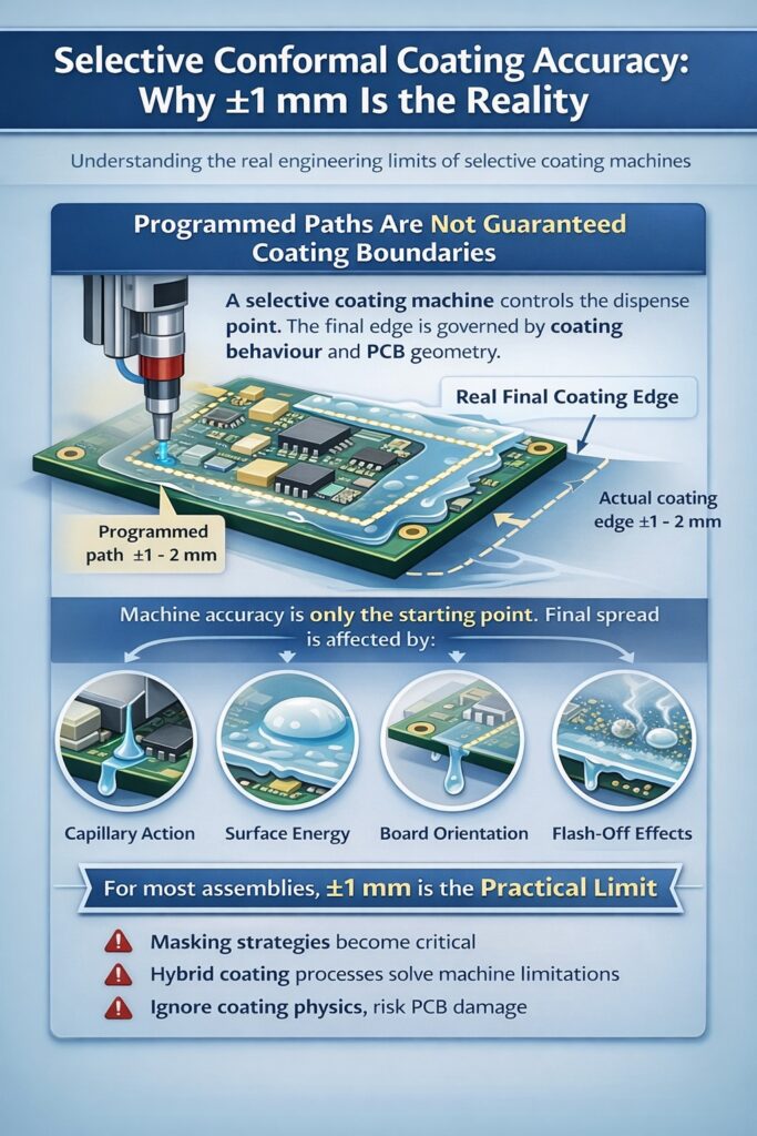
Selective conformal coating accuracy is governed by coating behaviour and PCB geometry, with typical real-world boundary variation of ±1–2 mm.
1) What selective coating machines actually control
A selective coating system controls several important starting conditions.
- Valve opening and closing
- Travel path and speed
- Application height
- Overlap pattern
- Repeatability of programmed motion
These are important, but they are not the final coating boundary. The final edge is still determined by how the coating behaves once it touches the PCB.
2) Why the final coating edge moves
Once material is applied, several physical effects take over.
- Wetting: the coating spreads across the surface depending on surface energy.
- Levelling: the film moves after dispense to reduce surface tension gradients.
- Capillary action: material is pulled into gaps, holes and under components.
- Gravity and board orientation: the liquid can creep or drain before curing.
- Flash-off behaviour: solvent loss changes viscosity during and after application.
The final coating position is therefore a combination of machine settings, liquid physics, surface condition and PCB geometry.
This is why selective coating accuracy should be considered alongside surface preparation, application method and wider process control.
3) Why ±1 mm is often the real engineering number
In practical engineering terms, ±1 mm is often the best realistic boundary expectation under good conditions. In routine production, ±2 mm is commonly a safer design assumption.
Production variation is introduced by several factors.
- Board finish and cleanliness
- Component height and density
- Coating viscosity and temperature
- Valve condition and atomisation quality
- Operator setup and fixture repeatability
If the keep-out zone is tighter than this, the process is already under pressure before production begins.
Coating accuracy, thickness consistency and viscosity control are directly linked. Many apparent accuracy issues are caused by process variation rather than machine capability.
For related process verification, see conformal coating thickness verification.
4) Tight geometries make the problem worse
Selective coating becomes more difficult when the PCB includes tight or mixed-function geometry.
- Fine-pitch features
- Dense component populations
- Connector boundaries
- Press-fit holes
- Mixed coated and uncoated areas
These assemblies create local flow paths, shadow zones and capillary routes that pull coating beyond the ideal programmed area.
For connector-heavy layouts, see Protecting Connector Interfaces Without Conformal Coating Them.
5) Low surface energy materials increase spread risk
The problem becomes more severe when using low surface energy coatings such as fluoropolymer and nano systems.
- They wet aggressively.
- They spread further after application.
- They migrate into smaller geometries more easily.
This is why a machine path that looks safe in software can still result in coating entering an unacceptable area in production.
Nano and fluoropolymer systems need careful boundary planning. See What Nano Coatings Can and Can’t Do on PCB Assemblies and Hybrid Conformal / Nano Coating Strategy for wider process context.
6) Why this matters around connectors and keep-out zones
Many assemblies fail not because the coating was placed badly, but because the keep-out assumption was unrealistic.
Typical high-risk areas include:
- Connector interfaces
- Test points
- Press-fit contacts
- Mechanical mating areas
- High-density zones requiring clean boundaries
If the design requires a crisp edge with almost no tolerance, selective coating alone may not be the correct process architecture.
This becomes especially important on complex boards where final edge control drives the whole process decision. See Why Conformal Coating Fails in Complex PCB Assemblies.
7) Common misconception: better programming solves the problem
It is tempting to believe the answer is simply better machine programming.
- More accurate path programming
- Slower travel speed
- A different valve pattern
- More passes with less material
These changes can improve the process, but they do not remove the underlying issue.
Reality check: The machine controls the dispense point. Liquid coatings still move after dispense.
8) What good process engineering looks like
A stronger engineering approach is to define the process around real capability.
- Set realistic keep-out distances.
- Design boundaries around coating behaviour, not software paths.
- Validate edge performance on representative boards.
- Use masking where boundary risk is too high.
- Consider hybrid process routes where selective coating alone is not enough.
This is how selective coating becomes reliable: not by pretending it is infinitely precise, but by designing around what it can actually do.
9) When selective coating is the wrong answer on its own
Selective coating on its own may be the wrong solution when the geometry or keep-out requirement is tighter than the process can reliably control.
- Critical interfaces sit very close to coated regions.
- Keep-outs are smaller than realistic spread tolerance.
- Connectors cannot tolerate even minor coating ingress.
- Complex geometries pull liquid into unintended areas.
- The board requires both strong protection and safe uncoated functional zones.
In these cases, the process may need to shift towards masking, hybrid coating strategies or a different protection concept.
Where selective coating cannot safely manage keep-outs on its own, a hybrid coating strategy often provides a more robust engineering route. If the issue is broader than selective coating itself, compare the wider options in Conformal Coating vs Nano Coating vs Parylene.
10) Key conclusion
Selective coating is repeatable, but it is not infinitely precise.
The machine controls the dispense point. Coating physics controls the final boundary.
For most real assemblies, ±1 mm is the practical reality. Engineers who design around that truth build more stable coating processes than those who design around the software drawing alone.
If the required boundary control is tighter than this, the issue is not only machine accuracy but process suitability. At that point, it is worth considering alternative coating strategies.
Related process articles
Selective coating accuracy should be reviewed alongside surface preparation, connector protection, thickness control and wider process capability.
- Electronic Coating Process Control for Reliability
- Surface Preparation & Cleanliness for Reliable Coating
- Protecting Connector Interfaces Without Conformal Coating Them
- Hybrid Conformal / Nano Coating Strategy
- Conformal Coating Thickness Verification
- Why Conformal Coating Fails in Complex PCB Assemblies
Why Choose SCH Services?
SCH Services helps customers turn coating theory into workable process capability. We support selective coating development, masking strategy, boundary validation and process design so coating systems perform reliably in real production, not just in software.
This is especially important on assemblies with tight keep-out zones, connectors and mixed-function regions where boundary control defines success or failure.
- Conformal Coating Solutions
- Conformal Coating Services
- Conformal Coating Training
- Conformal Coating Consultancy
- Masking Solutions
- Support Equipment
For support with selective coating boundaries, masking strategy or coating process control, contact SCH Services.
This article is provided as general technical guidance only. Final design, process, safety and compliance decisions should be validated against the specific assembly, coating chemistry, production method, applicable standards and customer requirements.
