RF transparent coatings for electronics and antennas
How ultra-thin functional coatings can protect RF-sensitive assemblies without disrupting signal performance
RF-sensitive electronics and antenna assemblies often need environmental protection, but conventional coating thickness can create problems. Added dielectric material, uneven coating build, moisture retention or coating over critical surfaces can affect tuning, signal transmission, impedance behaviour or repeatability.
Ultra-thin functional coatings can offer a different route. Instead of creating a thick environmental barrier, they may provide surface-function benefits such as reduced wetting, liquid shedding and light-duty environmental resistance while keeping coating build extremely low.
This makes RF transparent coating selection a balance between protection, thickness, dielectric behaviour, process control and validation against the real antenna or RF system.
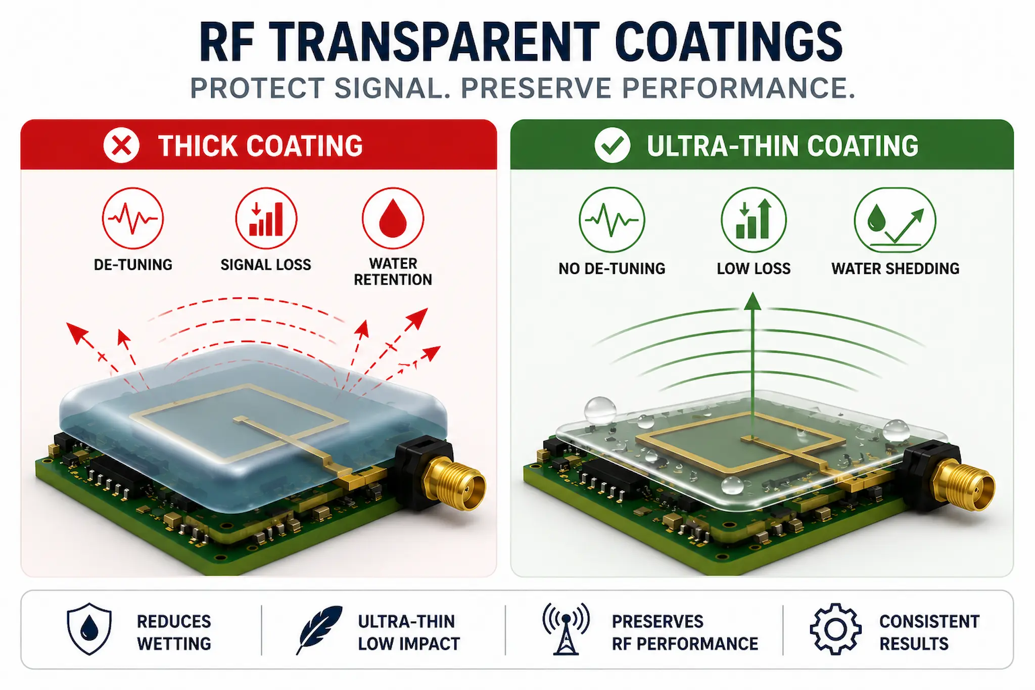
Ultra-thin RF transparent coatings can reduce wetting and environmental exposure while helping preserve RF performance.
Why RF assemblies are sensitive to coating choice
RF and antenna performance can be affected by materials placed near the radiating element, feed structure, ground plane, matching network or signal path. Even small changes can matter if the design has tight electrical tolerances.
Coating influence depends on the antenna type, operating frequency, coating material, coating thickness, dielectric constant, loss tangent, geometry and whether the coating is uniform or locally variable.
Common coating-related risks include:
- frequency shift: added dielectric material may alter antenna tuning;
- signal loss: lossy materials may reduce efficiency or range;
- repeatability issues: uneven thickness can create part-to-part variation;
- moisture retention: trapped water can change RF behaviour more than the coating itself;
- masking difficulty: critical RF areas may be hard to protect without affecting the design.
For RF assemblies, the coating is not just a protective layer. It becomes part of the electrical environment around the antenna.
This is why coating selection for RF applications must be validated using actual RF performance testing, not only visual inspection or general coating assumptions.
Why ultra-thin coatings can be useful
Ultra-thin functional coatings are attractive for RF applications because they minimise added material. Where coating thickness is very low and the material is selected appropriately, the risk of detuning or disrupting signal behaviour may be reduced compared with thicker coatings.
The main value is often surface behaviour rather than heavy barrier protection. These coatings may reduce water wetting, help droplets shed from the surface, reduce liquid retention and provide light-duty protection without significantly changing the physical geometry of the RF structure.
Very thin coatings can still fail if the wrong protection mechanism is assumed, the environment is too aggressive, contamination is uncontrolled or the coating is expected to behave like a full barrier system.
For broader limitations and selection risks, see Why Ultra-Thin Coatings Fail and When Nano Coatings Should NOT Be Used.
For related background on why water shedding and corrosion protection are not automatically the same thing, see Why Water Resistance Is Not Corrosion Protection.
Ultra-thin coatings may help where:
- the antenna or RF surface cannot tolerate conventional coating thickness;
- the design needs reduced wetting without heavy coating build;
- water retention is more problematic than brief surface exposure;
- masking critical RF features is difficult or inconsistent;
- low-profile protection is required on compact or precision electronics.
For background on the underlying coating function, see Surface Energy vs Environmental Barrier Protection.
The key point is that RF transparent coatings should be specified around the electrical behaviour of the assembly, not simply around the coating chemistry.
RF transparency does not remove the need for testing
A coating may be described as RF transparent, but that does not mean it can be applied to every antenna or RF assembly without evaluation. RF transparency is application-specific.
This reflects the wider difference between surface-function coatings and true environmental barrier protection discussed in Surface Energy vs Environmental Barrier Protection.
The same coating may behave differently depending on frequency, antenna geometry, coating thickness, local build-up, substrate material, moisture exposure and how the coating is applied.
RF transparency should be proven on the real assembly, at the real frequency, using the real coating process.
Validation may include:
- baseline RF measurement before coating;
- RF measurement after coating and cure;
- comparison of coated and uncoated samples;
- testing after humidity, condensation or water exposure;
- inspection for coating pooling, edge build or local thickness variation;
- repeatability checks across multiple parts or production batches.
Without this validation, an apparently low-risk coating may still introduce performance variation or reliability uncertainty.
Where RF transparent coatings may fit
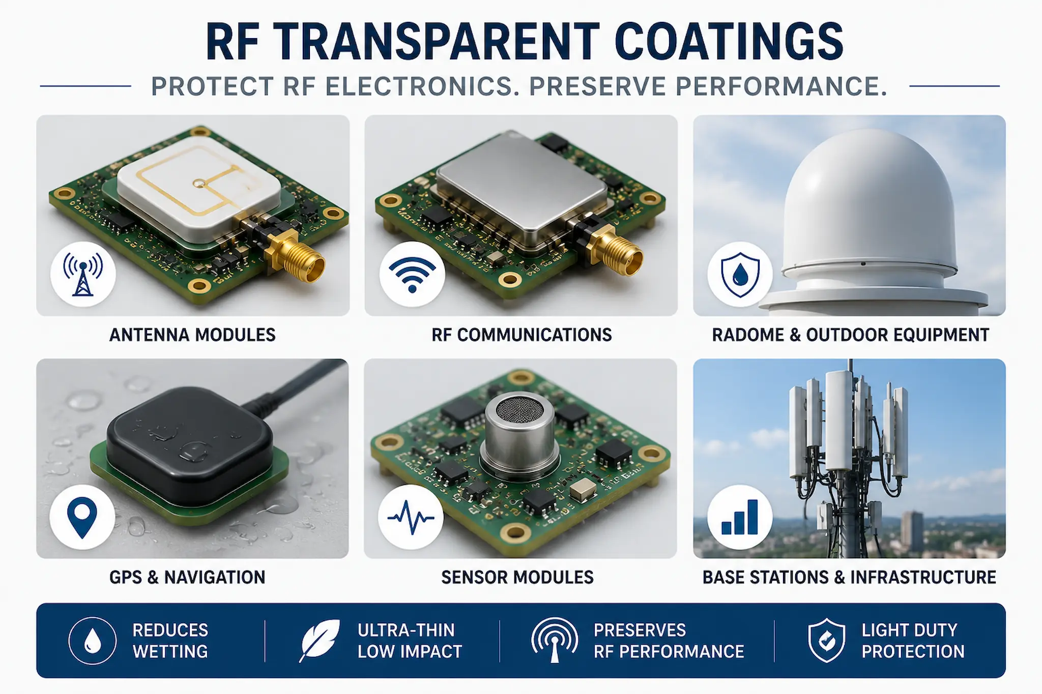
RF transparent ultra-thin coatings may help protect antenna modules, sensors and RF electronics without adding significant coating thickness.
RF transparent ultra-thin coatings are most relevant where the assembly needs reduced surface wetting or light-duty environmental protection, but conventional coating build may interfere with performance.
They are not automatically a substitute for conformal coating or Parylene where the main requirement is robust dielectric barrier protection, corrosion resistance or long-term environmental isolation.
Typical candidate applications include:
- antenna modules and compact RF electronics;
- radome-adjacent electronic surfaces;
- sensor and communications assemblies;
- outdoor or exposed electronics requiring reduced water retention;
- LED, optical or RF assemblies where coating build must be minimised;
- precision components where dimensional change must be controlled.
For related surface-function selection guidance, see What Is an Ultra-Thin Functional Coating and Surface Function vs Barrier Function Coatings.
The strongest use case is not “coat everything because it is thin”, but “use a low-build surface-function coating where thickness would otherwise create a design compromise”.
When a different coating route may be needed
Ultra-thin coatings are not the correct answer for every RF application. Some applications require surface-function behaviour, while others require robust environmental barrier protection, corrosion resistance or dielectric isolation. If the assembly needs long-term corrosion resistance, high dielectric protection, chemical resistance, abrasion resistance or full environmental sealing, a stronger barrier strategy may be needed.
In some cases, the best route may be selective coating, local masking, Parylene coating, conformal coating away from the RF-critical area, or a hybrid strategy that protects non-RF areas while leaving tuned features controlled.
Very thin coatings can still fail if the wrong protection mechanism is assumed, the environment is too aggressive, contamination is uncontrolled or the coating is expected to behave like a full barrier system.
For broader limitations and selection risks, see Why Ultra-Thin Coatings Fail and When Nano Coatings Should NOT Be Used.
Consider an alternative route where:
- ionic contamination and corrosion are the primary risks;
- the assembly is exposed to long-term condensation or harsh service environments;
- the RF-critical area can be masked reliably;
- the design requires certified dielectric protection;
- mechanical durability is more important than surface wetting control.
For broader protection routes, see conformal coating solutions, Parylene coating solutions and advanced functional coatings.
The coating choice should always be driven by the failure mechanism, RF sensitivity and validation evidence.
Practical selection framework
| Question | Why it matters |
|---|---|
| What frequency range is involved? | Coating influence can change with operating frequency and antenna design. |
| Where is the RF-sensitive area? | Critical areas may need selective coating, reduced build or masking. |
| Is the goal water shedding or corrosion protection? | Surface-function and barrier-function requirements need different validation. |
| Can the coating be applied repeatably? | Thickness variation and local build-up can affect RF consistency. |
| How will performance be proven? | RF testing before and after coating is essential for confidence. |
This framework helps prevent a thin coating being over-specified as a full barrier system or dismissed too quickly where a low-build surface-function coating may be the better fit.
Practical takeaway
RF transparent coatings are most useful when environmental exposure needs to be reduced without adding meaningful coating thickness to a sensitive RF design.
They should be treated as application-specific surface-function coatings unless testing proves broader environmental performance.
The correct specification should combine coating selection, controlled application and RF validation on the real assembly.
Related coating selection routes
These pages may help when comparing RF transparent coatings with other electronics protection options:
Why Choose SCH Services?
SCH Services supports electronics manufacturers with coating selection, process development, application trials and production coating services across conformal coatings, Parylene coatings and advanced functional coatings.
We help customers separate coating claims from real process requirements by reviewing the application, exposure conditions, masking limits, inspection route, coating thickness and validation method.
- Technical coating experience: practical support across conformal coating, Parylene and ultra-thin functional coating applications.
- Process-led approach: coating selection based on failure mechanism, production reality and validation evidence.
- Application support: assistance with trials, masking, inspection, coating thickness and process control.
- Production capability: subcontract coating services and engineering support for specialist electronics protection requirements.
To discuss whether an ultra-thin RF transparent coating, conformal coating, Parylene coating or hybrid strategy is the right route for your application, contact SCH Services for technical support.
This article is provided as general technical guidance only. RF coating selection, antenna performance, environmental protection and reliability decisions should always be validated against the relevant application requirements, operating environment, standards, qualification tests and customer specifications.
