Dip Coating Process Control: From Fluid Behaviour to Production Stability
How dip coating film formation and process variables determine coating stability
Dip coating is often described as a simple application method, but good results do not come from immersion alone. Final coating thickness, edge definition, coverage consistency and defect profile are all driven by how the liquid behaves during entry, withdrawal, drainage and cure.
Small changes in viscosity, geometry, masking, immersion profile or withdrawal speed can produce very different outcomes. A process that appears stable on one assembly can become inconsistent when the design, material, ambient conditions or operator technique changes.
This article explains dip coating as a process system rather than a single step. It sits above the more practical guide to how to run a dip coating process on a PCB and the supporting article on dip coating equipment settings and process control variables.
For a broader view of how instability develops on demanding assemblies, see why conformal coating fails on complex PCB assemblies. For a broader root-cause view of repeated coating failures, see Why Conformal Coating Fails. If defects are already visible, use Top Conformal Coating Failure Mechanisms to route the symptom back to the likely process cause.
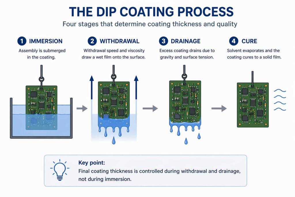
Film thickness in dip coating is created during withdrawal and then modified during drainage — not during immersion.
Why dip coating is often misunderstood
Dip coating can look straightforward because the visible action is simple: immerse the assembly, withdraw it, allow the coating to drain, then cure. In practice, the coating film is formed dynamically during withdrawal and then modified again by gravity, surface tension, capillary effects and solvent evaporation.
- Film thickness is created during withdrawal, not immersion
- Drainage changes the coating after the dip
- Geometry alters local coating behaviour
- Process stability depends on controlling multiple variables
This means good dip coating is not defined by whether the board has been coated. It is defined by whether the process produces the required thickness, the correct coverage, acceptable boundary control and a low-defect finish on a repeatable basis.
The mistake many teams make is to treat dip coating as a low-complexity manual method. In reality, it is a fluid control process. If the process window is not understood, variation appears quickly as runs, pooling, creeping, wicking, excessive thickness, thin edges or unstable results between batches.
How the coating film is formed
The final film does not simply “stick” to the assembly at a fixed thickness. As the assembly is withdrawn from the coating tank, a wet film is drawn onto the surface. That wet film is influenced by coating viscosity, withdrawal speed, liquid surface behaviour, substrate wetting and the local geometry of the assembly.
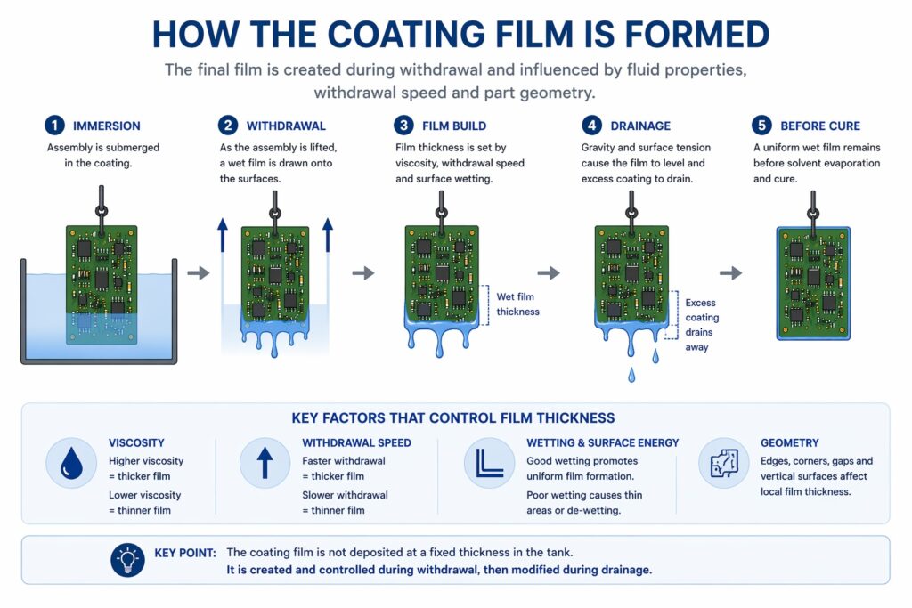
The coating film is created during withdrawal and then influenced by viscosity, speed and drainage behaviour.
In general terms, higher viscosity tends to leave a heavier wet film, while faster withdrawal can also increase film build. However, neither variable should be viewed in isolation. The actual result depends on the coating chemistry, thinner content, bath condition, ambient temperature, product geometry and the time available for the wet film to drain before flashing off or curing.
This is why a process can appear correct on flat coupons but perform very differently on populated assemblies. The board is not a uniform surface. Leads, connectors, corners, component bodies, standoffs and masked areas all alter how the liquid behaves during film formation and drainage. This is also why different coating methods behave differently, as outlined in conformal coating application processes.
What engineers should take from this
- Film thickness is created by process behaviour, not only by material choice.
- Withdrawal speed and viscosity are linked variables, not independent settings.
- Assembly geometry changes the local coating outcome even when the global settings remain the same.
- Any meaningful dip coating process must be validated on representative assemblies, not idealised flat test pieces alone.
Drainage is where many dip coating results are won or lost
Once the assembly leaves the tank, the coating continues to move. Gravity begins pulling excess liquid downward, while surface tension attempts to retain a continuous film. During this stage, the coating redistributes around edges, vertical surfaces, lower features and trapped geometries.
If the wet film is too heavy for the assembly design, drainage can produce sagging, thick lower edges, bridging or pooled regions. If the film is too light, the coating may drain excessively from critical surfaces, leaving lower-than-expected coverage or exposing sensitivity to de-wetting and edge recession.
Drainage behaviour is one of the reasons controlled dwell, withdrawal and post-dip handling matter so much. A board that is tilted, paused inconsistently or moved too soon after withdrawal can shift the liquid before the film stabilises. This is also why the same coating chemistry may behave well in one line and inconsistently in another.
It is also critical that excess coating drains from beneath components rather than remaining trapped in local pockets. Where heavy retained coating sits under devices, the resulting thickness build can create mechanical stress during cure and later thermal cycling. In assemblies with strong CTE mismatch between the conformal coating, component materials and the PCB structure, this can contribute to cracking, interfacial damage or, in extreme cases, component lift.
Common drainage-related outcomes
- Runs or curtains on long vertical features
- Pooling at lower edges or beneath large components
- Heavy accumulation around connectors, lead exits or masked boundaries
- Uneven coating build between the top and lower areas of the same assembly
For related defect mechanisms, see the defect articles on air entrapment, bubbles and foam in conformal coating, de-wetting and poor wetting behaviour and capillary flow and wicking during coating. Where retained build later creates stress-related damage, cracking in conformal coating is also relevant.
Why assembly geometry changes everything
Dip coating does not behave the same on every product. A sparsely populated board with good spacing and simple stand-off components may drain cleanly and predictably. A dense assembly with tall parts, narrow gaps, underside features, wire exits or masked interfaces may trap coating, encourage capillary movement or create local thickness build-up.
Geometry matters because fluid movement is local as well as global. The same dip profile can produce one thickness on a flat zone, another around sharp edges, and a third in a narrow gap where capillary attraction or restricted drainage holds liquid in place.
This is why process development should always consider the real assembly architecture. Engineers should not ask only “what coating are we using?” They should also ask:
- Where will coating collect?
- Where will it drain away too quickly?
- Where can air become trapped on immersion?
- Where can liquid wick into restricted spaces or under masks?
- Which features will define the visual and functional accept/reject criteria?
Surface condition and wetting still control success
A well-controlled mechanical dip profile cannot compensate for poor wetting. If the substrate surface is contaminated, has low surface energy in critical zones, or carries residues from previous handling, the coating may pull back, separate, form islands or expose local thin areas.
This matters because some dip coating defects are incorrectly blamed on machine settings when the true cause sits upstream in cleaning, handling or material compatibility. Surface preparation remains fundamental even when the application method is well controlled.
Wetting problems commonly show up as de-wetting, edge retreat, local thinning or unstable cosmetic finish. These issues often become more visible after cure but originate much earlier in the process.
Typical upstream causes of wetting instability
- Residues from flux, cleaning chemistry or handling
- Silicone or release-agent contamination
- Poorly controlled drying before coating
- Material combinations that challenge the selected coating chemistry
For broader background, see de-wetting in conformal coating, corrosion, ionic contamination and coating failure and surface preparation and cleanliness for reliable conformal coating.
Masking and boundary control are part of dip process design
Dip coating is not only about the coated area. It is equally about the non-coated area and how reliably that boundary is maintained. In many assemblies, the practical difficulty is not achieving coverage but stopping the coating from creeping, pooling or wicking into excluded zones.
Masking performance depends on more than mask placement. The shape of the boundary, the pressure of the masking interface, the compatibility of the masking method with the coating, and the fluid behaviour during withdrawal all affect whether the mask line remains clean and stable.
This is especially important around connectors, wire exits, high-density interfaces and areas where liquid can be drawn by capillary action. A masking approach that appears adequate during setup may fail once the process is run repeatedly or once viscosity drifts during production.
Boundary questions that should be reviewed during process development
- Is the masking method mechanically stable through the dip cycle?
- Will the fluid tend to pool against the mask edge?
- Can the coating wick past the boundary during withdrawal or drainage?
- Is the design expecting a cosmetic edge or a functional edge?
- Does the mask design remain robust as viscosity and temperature vary over time?
For deeper troubleshooting, see why masking creates many coating defects and capillary flow and wicking into unwanted areas.
The core process variables and how they interact
Although dip coating can involve many settings, most stable processes are built around a few core variables: coating viscosity, withdrawal speed, immersion profile, dwell time, bath condition, ambient temperature and post-dip handling. These should be viewed as an interacting set rather than as isolated controls.
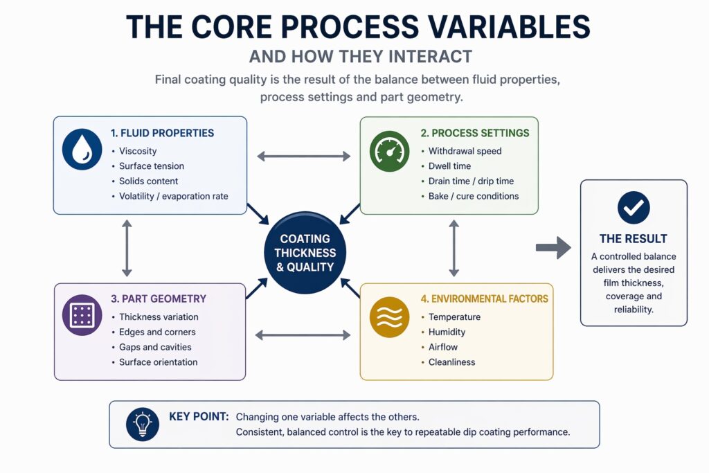
Coating thickness and quality are controlled by the interaction between fluid properties, process settings, geometry and environment — not a single parameter.
Viscosity
Viscosity strongly influences wet film build and drainage behaviour. As viscosity rises, the process tends to leave a heavier wet film and can become more sensitive to runs, thick lower edges and trapped material in dense geometries. As viscosity falls, the process may become more vulnerable to low build, edge recession or reduced coverage consistency. For practical measurement and control, see how viscosity is measured and controlled in a coating process.
Withdrawal speed
Withdrawal speed affects how much liquid is retained on the assembly as it exits the tank. It is one of the most important settings in dip coating, but it only has meaning when linked to a known viscosity range and representative product geometry. A speed that works on one product may be wrong for another.
Immersion profile
Immersion speed also matters. If the assembly enters the coating too quickly, air can become trapped around component leads, beneath devices and within restricted geometries. That trapped air may then bleed out during dwell, withdrawal or drainage, creating bubbles, voids or frog-eye type defects around leads and other difficult features. For related defect modes, see bubbles, pinholes and foam caused by air entrapment.
Temperature and solvent balance
Ambient temperature and solvent loss change the effective viscosity of the coating over time. Even when operators do not visibly change the process, the process can drift because the liquid is no longer behaving the same way as it did at the start of the batch.
Tank level and immersion condition
Stable liquid height, controlled entry and repeatable dwell all contribute to consistency. If tank level shifts, the product may experience different immersion geometry, different drainage paths and different effective exposure around critical features.
Post-dip handling
Movement immediately after withdrawal can change the coating distribution before the film stabilises. This is often overlooked in manual processes, where handling variation becomes an uncontrolled process variable.
For a more settings-focused view, see dip coating equipment settings and process control variables.
Why manual dip coating becomes unstable
Manual dip coating can be entirely appropriate for prototypes, lower volumes or early-stage process work. The problem is not that manual dipping is inherently wrong. The problem is that manual operations make it difficult to hold the critical variables within a stable window over time.
Operator technique can influence immersion smoothness, withdrawal speed, pause timing, part orientation and post-dip handling. At the same time, the bath may drift in viscosity, the tank level may change, and the product may vary between lots. When these factors combine, the process can become inconsistent even if each individual step appears reasonable.
This is why many teams believe they have a “coating issue” when they actually have a control issue. The coating chemistry may be acceptable, but the process does not hold the variables tightly enough to produce consistent results across shifts, batches or changing assemblies.
What controlled dip coating systems are really doing
Controlled dip systems do more than automate movement. Their real value is that they reduce process variation by making immersion, withdrawal and handling more repeatable, while also supporting tighter control of bath condition and operating discipline.
In practical terms, this means a controlled system can help maintain a known withdrawal profile, support more consistent film formation, reduce variation caused by handling differences and provide a better basis for process validation. The more sensitive the assembly is to thickness window, edge control or local defect risk, the more valuable this repeatability becomes.
This is also why a well-designed dip system should be viewed as a process control tool rather than only as labour-saving equipment. In many cases, the commercial value comes from reducing rework, narrowing variation and making the process more transferable between people, lots and products.
SCH discusses this more directly in the article on dip coating process settings and equipment control and in the practical guide to how to run a dip coating process on a PCB.
How engineers should approach dip coating development
A good dip coating development programme does not begin by selecting a speed and hoping for the best. It begins by defining the required coating outcome, identifying the geometrically sensitive areas, selecting the likely control variables, and then building a test plan around representative product conditions.
A practical development sequence
- Define the required thickness window, exclusion zones and cosmetic expectations.
- Review the assembly for trapped-air features, capillary paths, lower-edge build zones and masking sensitivity.
- Select the coating chemistry and establish a controlled viscosity window.
- Evaluate withdrawal speed against real assemblies rather than flat coupons alone.
- Evaluate immersion speed where air entrapment risk exists around leads, underside features or restricted geometries.
- Inspect where the coating is heaviest, where it drains away, and where defects begin to appear.
- Confirm that the process remains stable over time rather than only at the start of the trial.
- Capture the validated window as a controlled process, not an operator memory.
In practice, this validation often includes controlled viscosity checks and the use of witness or representative test coupons to confirm that the process remains within a defined window, although coupon results should never replace assessment of the real assembly geometry. See how witness boards and test coupons support coating validation and how coating thickness is verified in production.
For step-by-step execution, see how to run a dip coating process on a PCB. For a broader comparison of coating methods, see conformal coating application processes.
Related articles and next reading
- How to Dip Coat a PCB – practical step-by-step guidance for carrying out the process
- Conformal Coating Dipping: Process Controls – focused guidance on the variables that must be controlled
- Conformal Coating Application Processes – comparison of the main conformal coating application methods
- Conformal Coating Viscosity – Importance in Process Control – practical control of bath behaviour
- Surface Preparation & Cleanliness for Conformal Coating – upstream control of wetting and adhesion
- Conformal Coating Test Coupons & Witness Boards – validation using representative structures
- Thickness Verification Methods – measurement and control of coating thickness
- Why Conformal Coating Fails on Complex PCB Assemblies – why instability shows up more readily on difficult assemblies
- De-wetting in Conformal Coating – why wetting failure undermines coverage stability
- Pinholes, Bubbles and Foam – air entrapment and surface defect mechanisms
- Capillary Flow and Wicking – why liquid moves into unwanted areas
- Masking Causes Most Conformal Coating Defects – how masking design and execution affect dip outcomes
Why Choose SCH Services?
SCH Services supports conformal coating process development, production troubleshooting, training and equipment selection with practical engineering input built around real manufacturing constraints.
Where dip coating is being considered, the key question is not whether immersion is possible, but whether the process can be controlled to deliver stable, repeatable results.
- Conformal Coating Services: Production coating, trials and process support
- Training: Practical conformal coating training for operators and engineers
- Consultancy: Technical support for process improvement, validation and troubleshooting
Where appropriate, SCH can also help assess whether manual dip coating is sufficient or whether a more controlled system approach is needed to improve consistency and reduce risk.
Disclaimer:
This article is provided as general technical guidance only. Dip coating performance depends on product design, materials, cleanliness, coating chemistry, masking strategy, process controls and validation requirements. Final process settings, acceptance criteria and suitability for production use should always be confirmed through appropriate engineering trials, qualification work and applicable customer or industry standards.
