The hidden ignition risk in explosive and defence manufacturing environments
In explosive and defence manufacturing environments, non-sparking tools are widely used to reduce ignition risk from mechanical impact. Materials such as aluminium bronze, beryllium copper, brass, bronze and Monel are commonly selected because they reduce the risk of spark generation when tools are struck, dropped or scraped.
However, non-sparking does not automatically mean electrostatically safe. A tool can be resistant to mechanical sparking and still accumulate, retain or transfer static charge during handling.
This creates an important blind spot in explosive-zone safety: tool safety should be treated as a combined spark-control and static-control problem, not simply as a material selection issue.
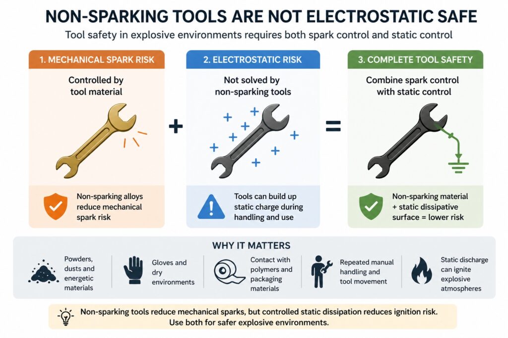
Non-sparking tools reduce mechanical spark risk but do not control static charge without dissipative surface behaviour
The Blind Spot in Explosive Zone Tooling
Non-sparking tools are designed to reduce the risk of ignition from mechanical impact. They do not inherently control electrostatic charge behaviour.
This matters in facilities handling energetic materials, propellants, pyrotechnics, ammunition components, explosive dusts, powders or sensitive assemblies.
Tools are not passive objects in these environments. They are repeatedly handled, moved across surfaces, brought into contact with packaging, used near polymers and often operated in dry processing areas.
Key insight: A tool can be non-sparking and still behave poorly from an electrostatic point of view.
That distinction is critical where static electricity is a recognised ignition source.
Explosive Zone Safety Is a Dual-Risk Problem
Tool safety in explosive environments should be viewed as two related but different risks.
| Risk Type | Typical Control | Limitation |
|---|---|---|
| Mechanical spark ignition | Non-sparking tool alloys | Does not control static charge |
| Electrostatic ignition | Controlled charge dissipation | Often not considered at tool level |
Aluminium bronze, beryllium copper, brass and other non-sparking materials address the mechanical side of the risk.
They do not automatically provide controlled electrostatic behaviour at the surface where operators hold, move and use the tool.
Where Static Charge Risk Can Develop
Static charge risk is most likely to develop where tools are part of repeated manual handling and movement.
- Tools handled with gloves
- Tools moved across benches or trays
- Tools used near polymers, films or packaging
- Tools used around powders, dusts or energetic materials
- Tools used in dry or low-humidity environments
- Tool holders, racks, trays, jigs and accessories used repeatedly in the same process
In these situations, the tool surface becomes part of the electrostatic control problem.
The question is not only whether the tool avoids mechanical sparks. It is also whether the tool surface can dissipate charge in a predictable and repeatable way.
Where ProShieldESD Fits
ProShieldESD can be positioned as a functional surface-safety enhancement for approved non-sparking tools and accessories.
It should not be presented as a replacement for certified tool material selection, hazardous-area classification, grounding, bonding, operating procedures or formal safety validation.
Its value is in helping introduce controlled electrostatic charge dissipation behaviour to frequently handled surfaces.
This may include tool handles, holders, trays, jigs, racks, maintenance accessories, separation pads and other contact surfaces used near energetic materials.
Positioning statement: The base tool alloy reduces mechanical spark risk. ProShieldESD supports controlled surface charge dissipation.
This creates a more complete approach: non-sparking metallurgy plus controlled dissipative surface behaviour.
Why Surface Behaviour Matters Over Lifecycle
In safety-critical environments, a single surface resistance reading is not enough. The surface behaviour must remain stable through handling, cleaning, wear and environmental change.
Filler-loaded conductive coatings can sometimes suffer from uneven conductive pathways, local variation, abrasion-related change or inconsistent performance across the surface.
Filler-free ProShieldESD technology is based on an intrinsically conducting polymer approach, which supports more homogeneous static-control behaviour across the coated surface.
For defence and explosive-zone users, this matters because predictable behaviour over the lifecycle is more important than a one-off headline reading.
Practical Defence Applications
ProShieldESD-coated tool systems may be relevant where approved non-sparking tools and accessories are used near static-sensitive or ignition-sensitive materials.
| Area | Example Items | Intended Benefit |
|---|---|---|
| Energetic material assembly | Tool handles, holders, trays, torque-tool grips | Reduce static build-up during repeated manual handling |
| Ammunition and fuze manufacturing | Jigs, fixtures and small-part handling tools | Support controlled charge dissipation near sensitive components |
| Propellant and pyrotechnic processing | Scrapers, scoops, bench accessories and racks | Lower the risk of charge accumulation on contact surfaces |
| UXO and EOD support environments | Non-sparking tool grips, cases and separation pads | Add controlled dissipative behaviour to field-handled accessories |
| Defence electronics with energetic integration | Workbench tools, fixtures and component trays | Support ESD-safe handling alongside explosive-area controls |
The strongest applications are not necessarily the tools themselves, but the complete tool-handling system: tools, trays, holders, fixtures, racks and storage interfaces.
Implementation and Validation
ProShieldESD should only be applied after confirming compatibility with the tool substrate, cleaning method, chemical exposure, abrasion level and operating environment.
Validation should be carried out in the actual tool configuration, not only on flat test panels.
- Surface resistance
- Point-to-point resistance
- Resistance-to-ground in the assembled tool system
- Adhesion to the selected tool substrate
- Wear and handling resistance
- Cleaning and solvent resistance
- Humidity stability
- Periodic verification method
It should also be integrated into the wider ESD and explosive-area control programme, including grounding, bonding, conductive flooring, operator footwear, wrist or heel straps where applicable, and documented inspection procedures.
The objective is not to claim that a coated tool becomes explosion-proof. The objective is to improve the control and repeatability of electrostatic behaviour on frequently handled surfaces.
Final Insight
Non-sparking tools solve only part of the ignition-risk problem.
They reduce the risk of mechanical sparks, but they do not automatically control electrostatic charge accumulation or transfer.
In explosive and defence manufacturing environments, this creates a hidden risk interface: the tool surface itself.
ProShieldESD can support a higher-confidence ESD-control surface on approved non-sparking tools and accessories, helping facilities reduce one of the least visible ignition risks: uncontrolled static charge accumulation during manual handling near energetic materials.
Related ProShieldESD Reading
Why Choose SCH Services?
SCH Services supports customers with technically led coating selection, process development and production implementation for demanding electronics, industrial and specialist manufacturing environments.
- Practical coating and surface-engineering experience
- Support with material selection, testing and validation
- Application-led advice rather than generic product supply
- Experience across conformal coating, Parylene, advanced functional coatings and ProShieldESD static-control coatings
For support with static-control coating selection, surface behaviour, process validation or ProShieldESD applications, contact SCH Services to discuss your requirements.
This article is general technical guidance only. It does not replace hazardous-area assessment, explosive atmosphere classification, safety certification, ESD programme design, material compatibility testing or formal process validation. Final decisions must be verified against the applicable standards, site procedures, operating environment and qualification requirements.