
Electrochemical Migration (ECM) & Dendrite Growth in Conformal Coating
How ionic contamination, moisture and electrical bias create leakage currents, dendrites and hard shorts under coating
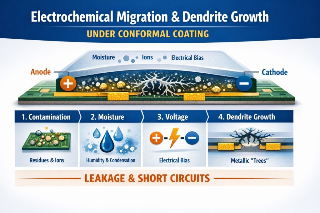
Electrochemical migration (ECM) and dendrite growth under conformal coating are among the most difficult reliability mechanisms to diagnose because early-stage failures are often intermittent, humidity-dependent and visually hidden. The mechanism develops when ionic contamination, moisture and electrical bias combine to form an electrolyte path that allows metal ions to move between conductors.
This is not simply a coating defect. Prevention depends on controlling cleanliness, dry-out, coverage and boundary quality before and during coating. Conformal coating can slow the mechanism, but it cannot compensate for contamination already present on or trapped within the assembly.
For a wider view of upstream process control, see the Conformal Coating Processes Hub and the Inspection & Quality Hub.
Article Quicklinks
| Topic | More |
|---|---|
| Definitions: ECM, dendrites, leakage currents, insulation resistance | 🔗 |
| How it happens: the ECM mechanism under conformal coating | 🔗 |
| Root causes: contamination sources, moisture pathways and electrical drivers | 🔗 |
| Prevention: cleanliness, dry-out, boundary control and control plan | 🔗 |
| Troubleshooting & diagnosis: SIR, humidity-bias replication, IC and FA | 🔗 |
| Repair: when to touch-up vs strip and recoat | 🔗 |
What is electrochemical migration (ECM) and dendrite growth?
- Electrochemical migration (ECM): metal ions dissolve at one conductor, usually the anode, and redeposit toward another conductor under electrical bias.
- Dendrites: filamentary metallic growths that can bridge conductor gaps and create leakage currents progressing to hard shorts.
- Insulation resistance (IR / SIR): a practical measure of how well adjacent conductors remain electrically isolated. ECM typically appears as insulation resistance degradation over time under humidity and bias.
- Electrolyte film: a thin moisture layer containing ionic contamination that enables ion transport between conductors.
Even with conformal coating present, ECM can still occur when moisture reaches ionic residues through thin edges, voids, interfaces or boundary zones. Coating can slow the mechanism, but it cannot neutralise contamination already on the assembly.
How ECM happens under conformal coating
- Step 1 — ions remain on the surface: residues persist after assembly, rework, fabrication, handling or cleaning drift. Under-component residues are often the highest risk because they are hard to remove and hard to inspect.
- Step 2 — moisture becomes available: humidity cycling, condensation, ingress at edges and boundaries, or moisture trapped before coating creates an electrolyte film.
- Step 3 — electrical bias drives movement: leakage begins, metal ions migrate and conductive dendrites form between biased conductors.
- Step 4 — weak areas amplify the failure: thin edges, shadowing, micro-voids, interfaces and keep-out boundaries concentrate moisture and accelerate migration.
Pattern clue: ECM typically presents as humidity-sensitive leakage or intermittent failure that progresses to hard shorts under bias.
Important: Coating defects such as pinholes, voids or dewetting do not cause ECM on their own, but they can significantly increase risk by allowing moisture access to contaminated surfaces. Where these defects are present alongside contamination, they often act as acceleration points for failure.
Related article: SIR failures are often an earlier electrical warning stage of the same contamination-and-moisture problem. For the wider electrical leakage perspective, see SIR Failures & Leakage Under Conformal Coating.
Root causes of ECM and dendrite growth
Contamination sources
- Flux residues from assembly or rework, especially in fine-pitch regions and under low-standoff parts.
- PCB fabrication residues such as etch, plate, solder mask or handling-related chemistry remnants.
- Inadequate washing and rinsing that leaves ionic or partly soluble residues on the surface.
- Contaminated wash or rinse systems that redistribute contamination rather than remove it.
- Handling contamination including fingerprint salts, glove transfer, dust or fibres.
Triggers
- Moisture exposure from humidity cycling, condensation, trapped wash water or insufficient dry-out.
- Electrical bias across conductors, particularly with higher voltage differentials and tighter conductor spacing.
- Coverage weaknesses such as thin edges, shadowing, keep-out boundaries and poor sealing around interfaces.
- Process escapes including rework not re-cleaned, uncontrolled queue times or poor compatibility between flux, cleaner and coating system.
Important: residue condition matters as much as residue presence. Controlled no-clean residues may remain stable in some processes, but excessive, inconsistent or partially disturbed residues can increase ECM risk sharply. For a focused explanation of that point, see Cleaning No-Clean Flux Residues for Conformal Coating Reliability.
Diagnostic cross-check: If you also see corrosion products or under-film attack patterns, review Corrosion, Ionic Contamination and Conformal Coating Reliability. If masking contamination or transfer is suspected, review Why Masking Causes Many Conformal Coating Defects.
How to prevent ECM and dendrite growth under conformal coating
1) Control cleanliness and residues
- Validated wash, rinse and dry processes: define windows, monitor performance and control drift where cleaning is used.
- Cleaning verification: ROSE can support trend monitoring on comparable builds, while ion chromatography helps identify ionic species and trace root causes on higher-risk products.
- Rework discipline: re-clean after rework where required, control flux application and avoid assuming that “no-clean” automatically means “no risk”.
2) Control moisture
- Controlled dry-out or pre-bake: remove absorbed moisture before coating, validated against the actual assembly and component constraints.
- Queue-time rules: define maximum time between clean and coat, and control storage conditions to limit re-absorption and re-contamination.
- Handling controls: gloves, no bare-hand contact, clean work surfaces and segregation of contamination sources.
3) Control barrier integrity
- Film build and edge coverage: avoid thin edges, shadowing and poorly sealed boundaries that admit moisture.
- Boundary quality: ragged keep-out edges and contaminated masking can create capillary pathways.
- Inspection plan: combine UV and white-light inspection where needed, and verify thickness using defined checks supported by the Inspection & Quality Hub.
If ECM is recurring, treat it as a control-plan gap rather than a one-off defect. Release criteria should cover cleanliness, dry-out and boundary integrity, not just whether the part has been coated.
Related article: ECM risk is one reason high-reliability workmanship frameworks place so much emphasis on verified cleanliness and disciplined process control. For a broader interpretation of those principles, read What NASA Gets Right About Conformal Coating.
Troubleshooting and diagnosis
1) Confirm the failure signature
- When it appears: humidity dependence, condensation exposure, post-wash events and no-fault-found returns are common ECM flags.
- Location logic: edges, interfaces, under-component regions, shadow zones and keep-out boundaries are common moisture pathways.
- Visual confirmation: dendrites may be hidden under coating, so local strip and microscopy are often required.
2) Quantify contamination and behaviour
- ROSE testing: useful for drift monitoring and comparisons on like-for-like builds.
- Ion chromatography: identifies ionic species and helps trace their source.
- Surface insulation resistance (SIR) or humidity-bias testing: replicates the risk under controlled bias and humidity conditions and helps assess margin.
3) Audit the process chain
- Cleaning audit: chemistry control, filtration, rinse quality, change-out rules and drying effectiveness.
- Dry-out verification: confirm moisture removal for the real assembled population, not just bare boards.
- Coverage and boundary audit: review thin edges, shadowing, keep-out boundaries and ingress paths.
Repair: when to touch-up vs strip and recoat
- Localised moisture or coverage weakness with verified clean substrate: controlled local removal, re-cleaning and touch-up can be acceptable where access and inspection are robust and the customer specification allows it.
- Confirmed ECM or dendrites: treat this as a systemic contamination and moisture-control failure. Strip, re-clean, verify and then recoat is usually the only reliable approach.
- Hidden under-component risk: if you cannot inspect or verify the attacked area, assume the mechanism may remain active and escalate accordingly.
For removal workflows and best-fit methods, see the Removal & Rework Hub.
Looking for other defect types?
This page covers electrochemical migration and dendrite growth under conformal coating. For the complete index of defect mechanisms and supporting technical articles, go to the Conformal Coating Defects Hub.
Why Choose SCH Services?
You gain a complete, integrated platform for Conformal Coating, Parylene & ProShieldESD—plus equipment, materials and training—backed by decades of hands-on process support.
- 🛠️ End-to-End Support – Selection, cleaning, masking, inspection and troubleshooting.
- ✅ Process Discipline – Recipes, control windows and repeatability.
- 🌍 Global Reach – Support across Europe, North America and Asia.
📞 Call: +44 (0)1226 249019 | ✉ Email: sales@schservices.com | 💬 Contact Us ›
This article is provided as general technical guidance only. Final process decisions should be validated against the specific assembly, contamination profile, coating chemistry, electrical design and applicable qualification or customer standards.
