
Defect Acceptance & Repair Rules for Conformal Coating
Defect acceptance & repair rules for conformal coating prevent inconsistent rework decisions, hidden reliability escapes, and “cosmetic fixes” that fail in test or the field. This page defines a structured, standards-aligned approach for deciding when a defect can be accepted, when controlled touch-up is allowed, and when strip & recoat is mandatory.
Use this as a governance page across the Defects Hub. Where defect mechanisms and root cause actions are needed, route through the Conformal Coating Defects Hub.
For removal workflows and best-fit methods, see the Removal & Rework Hub. For inspection discipline, see the Inspection & Quality Hub.
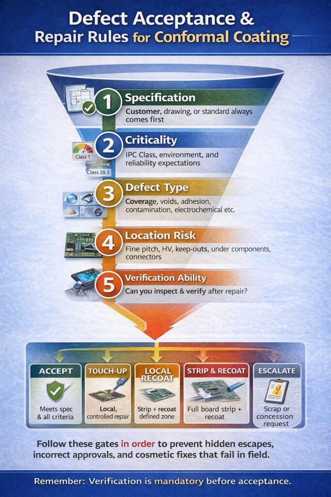
a five-step decision gate to determine accept, touch-up, local recoat, strip and recoat, or escalation based on specification, risk and verification.
Article Quicklinks
| Topic | More |
|---|---|
| What these rules cover: accept vs touch-up vs strip & recoat | 🔗 |
| The 5 decision gates: spec → criticality → defect type → location → verification | 🔗 |
| Acceptance rules: what can be accepted (and when) | 🔗 |
| Touch-up rules: when controlled repair is allowed | 🔗 |
| Strip & recoat triggers: when local repair is unsafe | 🔗 |
| Verification after repair: inspection, cure, thickness and (where needed) electrical checks | 🔗 |
What These Acceptance & Repair Rules Cover
- Acceptance — when the coating still meets functional intent and risk is controlled (including “cosmetic only” defects where allowed by spec).
- Controlled touch-up — local repair that restores protection without creating new risk (defined boundaries, compatible chemistry, verified outcome).
- Strip & recoat — required when defects indicate a systemic process issue, widespread contamination, hidden risk, or un-verifiable areas.
- Customer concession — required when acceptance is outside specification or the defect cannot be fully verified post-repair.
Important: “Looks OK” is not a repair criterion. Decisions must be based on risk, location, and the ability to inspect and prove compliance.
The 5 Decision Gates (Use This Order Every Time)
- Specification first — customer drawing / workmanship standard / coating spec always overrides local preference.
- Criticality — IPC Class expectations, duty environment (humidity/bias/thermal cycling), and consequence of failure.
- Defect mechanism — coverage/voids/adhesion/contamination/electrochemical mechanisms have different risk profiles.
- Location risk — fine pitch, HV, keep-outs, under components, connectors, edges, and interfaces amplify risk.
- Verification ability — if you can’t inspect and prove the repair, you can’t safely accept it.
Rule of thumb: the more the defect suggests contamination, adhesion loss, or electrochemical failure drivers, the faster you should escalate to strip & recoat.
Acceptance Rules: When a Defect Can Be Accepted
Acceptable (typical examples, subject to spec)
- Cosmetic texture variations that do not reduce coverage or create void pathways (e.g., mild orange peel where film build is compliant).
- Minor surface artefacts away from high-risk zones, where coating integrity is intact and inspection confirms coverage.
- Benign edge appearance that does not expose conductor, create moisture pathways, or violate keep-out requirements.
Do NOT accept if any of these apply
- Coverage is missing or thin on conductors, fine pitch, HV, or moisture-ingress pathways (route: insufficient coverage).
- Voids / pinholes / bubbles provide pathways for moisture/ions (route: pinholes, bubbles & foam and bubbles after cure).
- Adhesion loss (lift, peel-back, edge separation) suggests interface failure (route: delamination).
- Residues / contamination indicators imply ionic risk (route: corrosion & ionic contamination).
- Electrical symptoms (leakage / low SIR / intermittent short) are present (route: SIR failures and ECM/dendrites).
Acceptance must be evidence-based: if acceptance is allowed, record the defect type, location, inspection evidence, and the acceptance rationale.
Touch-Up (Finishing) Rules: When Controlled Repair Is Allowed
Finishing is usually acceptable when
- Defect is localised and the affected zone can be clearly bounded and fully inspected.
- Substrate is clean and dry (no contamination indicators; moisture risk controlled) and the mechanism is not systemic.
- Coating compatibility is controlled (same chemistry, within recoat window, or validated surface prep for recoat).
- Repair restores barrier integrity without creating edge lift, bridges, or solvent attack damage.
Touch-up controls (minimum expectations)
- Defined boundary — the repair zone must be mapped and documented (not “dabbed until it looks OK”).
- Surface prep — remove loose film, clean appropriately, and avoid introducing residues (masking transfer, glove contamination, silicone/oil).
- Recoat discipline — follow recoat windows; if recoating is involved, consider intercoat adhesion failure risk.
- Inspection — UV/white-light inspection + thickness verification where required by your control plan.
Finishing red flag: if the defect repeats after touch-up, treat as a systemic root cause and escalate to strip & recoat plus process audit.
Strip & Recoat Triggers: When Local Repair Is Not Safe
- Widespread defects across the assembly (indicates process window failure, contamination, or cure drift).
- Adhesion failures (lift/peel-back/delamination) suggesting interface contamination or compatibility problems.
- Void pathways across critical regions (pinholes/bubbles/foam) where moisture ingress risk is high.
- Electrochemical risk (low SIR/leakage/dendrites/CAF indicators) where contamination/moisture/bias mechanism may remain active.
- Hidden risk zones (under components, beneath conformal-coated interfaces, inside fine pitch areas) where verification is not possible.
- Recoat bonding risk when the first film is outside window, partially cured, contaminated, or incompatible (route: intercoat adhesion failure).
If strip & recoat is selected, treat it as a root cause event: document the trigger, capture the mechanism evidence, and close the loop with process control updates.
Verification After Repair (Don’t Skip This)
- Visual inspection — UV + white light where required; verify edges, interfaces, keep-outs, and fine pitch areas.
- Thickness verification — coupons, measurement points, or defined checks per your Inspection & Quality control plan.
- Cure confirmation — ensure cure profile is correct for the film build (watch thick zones, shadow areas, and recoat interfaces).
- Electrical checks (where applicable) — SIR/humidity-bias testing for high-risk products or where leakage mechanisms are suspected.
- Documentation — record the defect, decision outcome, repair method, and verification evidence for traceability.
If verification cannot be performed to the required standard, acceptance is not defensible — escalate to strip & recoat or customer concession.
Looking for a Specific Defect Mechanism?
This page defines conformal coating repair rules. For defect mechanisms, root cause diagnosis and prevention actions, use the complete index:
Training on Defect Acceptance & Repair Decisions
SCH delivers practical, standards-driven training covering defect identification, acceptance rules, controlled touch-up, and when to escalate to strip & recoat — plus the inspection discipline needed to prove compliance after rework.
Industry Standards We Work To
SCH Services aligns coating services, training, equipment supply and materials to relevant IPC standards, including:
- IPC-A-610 – Acceptability of Electronic Assemblies
- IPC-CC-830 – Qualification & Performance of Conformal Coatings
- IPC-HDBK-830 – Conformal Coating Handbook (guidance and best practice)
For further details on IPC standards: electronics.org/ipc-standards ↗
Explore Topic Hubs
Conformal Coating Processes Hub
Conformal Coating Equipment Hub
Conformal Coating Masking Hub
Conformal Coating Design Hub
Conformal Coating Defects Hub
Inspection & Quality Hub
Removal & Rework Hub
Standards Hub
Parylene Basics Hub
Parylene Design Hub
Parylene Application Hub
Parylene Dimers Hub
Why Choose SCH Services?
You gain a complete, integrated platform for Conformal Coating, Parylene & ProShieldESD—plus equipment, materials and training—backed by decades of hands-on process support.
- 🛠️ End-to-End Support – Selection, masking, inspection and troubleshooting.
- ✅ Process Discipline – Recipes, control windows and repeatability.
- 🌍 Global Reach – Support across Europe, North America and Asia.
📞 Call: +44 (0)1226 249019 | ✉ Email: sales@schservices.com | 💬 Contact Us ›
