
Bridging & Webbing Defects in Conformal Coating
Bridging (webbing) occurs when conformal coating forms a continuous film between two adjacent features that should remain electrically or functionally isolated — most commonly between pins, leads, pads, or test points in fine-pitch areas. This page explains how bridging forms, how to diagnose the dominant mechanism, and how to prevent recurrence.
For a complete index of defect types and links to each technical article, use the Conformal Coating Defects Hub.
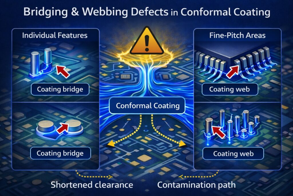
How conformal coating bridges and webs form between closely spaced pins and pads in fine-pitch areas
Article Quicklinks
| Topic | More |
|---|---|
| Definitions: what bridging/webbing is and when it matters | 🔗 |
| Root Causes: film build, viscosity, geometry and masking | 🔗 |
| Prevention: control window & recipes | 🔗 |
| Troubleshooting & Diagnosis: isolate the mechanism | 🔗 |
| Repair: when to remove vs rework | 🔗 |
What is Bridging / Webbing in Conformal Coating?
- Bridging — coating creates a continuous path between two adjacent conductors or features.
- Webbing — a thin “film web” spanning between pins/leads/pads (often seen in fine pitch or tight clearances).
- Typical locations — connector pins, fine-pitch leads, adjacent test pads, closely spaced terminations, and tight RF keep-outs.
- Main risk — reduced creepage/clearance, trapped residues/moisture, leakage under bias, or interference with test/mating functions.
Bridging should be assessed against the drawing/specification (keep-outs, minimum clearances, and acceptance rules). A bridge that is acceptable in one design may be a nonconformance in another.
Root Causes of Bridging & Webbing
Process & Technique
- Over-wet film build — heavy single-pass application leaves a mobile film that can span gaps before skinning or set.
- Keep-wet overlap effects — repeated overlaps or slow application speed maintain a continuously wet zone that promotes web formation.
- Application angle and distance — poor approach angles or excessive standoff can deposit film across gaps rather than around individual features.
- Orientation and gravity — pooling at low points allows coating to flow between adjacent leads or pads.
- Thick fillets acting as stress concentrators — heavy build between adjacent features cures into a rigid fillet that is more prone to cracking or crazing under thermal or mechanical stress, creating secondary moisture ingress paths.
Material & Condition
- Low viscosity / high flow — increases the tendency for coating to span fine gaps and tight clearances.
- Long open time — extended film mobility allows bridges to form before the coating locks.
- Solvent imbalance — unintended dilution or retained solvent alters flow behaviour and increases bridging risk.
Geometry & Masking
- Fine pitch / tight spacing — closely spaced pins and pads naturally promote bridging and webbing.
- Connector and recessed geometries — cavities and interfaces encourage local film build and web formation.
- Incorrect masking strategy — keep-outs that are unmasked or under-masked at high-risk features (connectors, test pads, mating faces) allow coating to bridge prohibited areas.
Sanity check (look-alikes):
- If coating is found within defined keep-out or prohibited areas, see coating ingress into keep-out areas.
- Where the issue is primarily excessive build or pooling at low points, see pooling / puddling.
- If thin or bare zones are observed behind tall components, see insufficient coverage / shadowing.
- Where cracking initiates at bridged or over-built areas, see cracking in conformal coating.
How to Prevent Bridging / Webbing
Stabilise the control window
- Multiple thin coats with defined flash-off rather than one heavy wet deposit.
- Control viscosity: measure/record and keep within a validated range.
- Manage open time: avoid films that remain mobile long enough to span tight gaps.
Reduce keep-wet bridging behaviour
- Optimise overlap and speed in dense component fields to avoid persistent wet zones.
- Tune local parameters near fine pitch: flow, pressure, distance and dwell should be reduced where practical.
- Use multi-angle strategy carefully to avoid laying continuous films across pin rows.
Keep-out protection (where required)
- Mask high-risk features (connectors, test pads, mating surfaces) using suitable tapes, boots, dots or custom masks.
- Mask-edge sealing where appropriate to stop creep under the boundary.
- Inspect pre-cure so ingress/webbing can be removed before full cure.
For masking methods and keep-out control strategies, use the Masking Hub. For inspection planning and acceptance routines, use the Inspection & Quality Hub.
Troubleshooting & Diagnosis
1) Confirm the bridge and the risk
- UV + white-light inspection: confirm continuous films spanning adjacent conductors/features.
- Confirm keep-out and clearance rules: check drawings/specs for prohibited zones and minimum separation.
2) Identify the dominant mechanism
- Pattern repeatability: recurring bridge locations usually indicate geometry + recipe/path issues.
- Film mobility: determine whether bridging occurs while wet, during flash, or during cure.
- Keep-wet behaviour: look for overlaps and dwell that maintain wet films in dense fields.
3) Validate with A/B trials
- Reduce flow/overlap or add flash steps; confirm bridging reduces without creating shadowing elsewhere.
- Where required, add or improve masking and verify ingress is eliminated.
Repair: When to Rework vs Remove and Recoat
- Localised webbing in accessible areas: controlled local removal may be possible if you can re-inspect and verify clearance.
- Bridging in connectors, contacts, or defined keep-outs: treat as a high-risk nonconformance — removal and rework is usually required.
- Recurring bridging: fix the process window and application recipe before reworking, otherwise the defect will repeat.
For structured removal workflows and best-fit methods, see the Removal & Rework Hub.
Looking for Other Defect Types?
This page covers bridging and webbing. For the complete index of defect types and links to each technical article:
Training on Conformal Coating Defects
SCH offers conformal coating training that goes beyond theory—recognising and preventing bridging/webbing, coating ingress into keep-outs, insufficient coverage, wicking, pinholes/bubbles/foam, orange peel, de-wetting, and corrosion mechanisms. We cover process analysis, troubleshooting, materials, and application methods.
Industry Standards We Work To
SCH Services aligns coating services, training, equipment supply and materials to relevant IPC standards, including:
- IPC-A-610 – Acceptability of Electronic Assemblies
- IPC-CC-830 – Qualification & Performance of Conformal Coatings
- IPC-HDBK-830 – Conformal Coating Handbook (guidance and best practice)
For further details on IPC standards: electronics.org/ipc-standards ↗
Explore Topic Hubs
Conformal Coating Processes Hub
Conformal Coating Equipment Hub
Conformal Coating Masking Hub
Conformal Coating Design Hub
Conformal Coating Defects Hub
Inspection & Quality Hub
Removal & Rework Hub
Standards Hub
Parylene Basics Hub
Parylene Application Hub
Why Choose SCH Services?
You gain a complete, integrated platform for Conformal Coating, Parylene & ProShieldESD—plus equipment, materials and training—backed by decades of hands-on process support.
- 🛠️ End-to-End Support – Selection, masking, inspection and troubleshooting.
- ✅ Process Discipline – Recipes, control windows and repeatability.
- 🌍 Global Reach – Support across Europe, North America and Asia.
📞 Call: +44 (0)1226 249019 | ✉ Email: sales@schservices.com | 💬 Contact Us ›
