Masking Design Guidelines for PCBs & Assemblies
Designing Keep-Out Areas That Can Be Masked Reliably
Masking success in conformal coating processes is largely determined before a PCB ever reaches the coating line. Poorly defined keep-out areas, inaccessible geometry, and inconsistent spacing force operators to improvise during masking, increasing defect risk, rework time, and inspection failures.
This guide explains how to design PCBs and assemblies so masking can be applied consistently, repeatably, and cleanly using standard masking materials and methods. The aim is not to eliminate masking, but to make it predictable and controllable.
For operator technique and application discipline, see Masking Application Best Practices. For material selection constraints that influence design, see Masking Material Selection for Conformal Coating.
PCB design guidelines for reliable masking in conformal coating, covering keep-out definition, spacing, boundary geometry, and defect prevention.
Defining Masking Keep-Out Areas for Conformal Coating
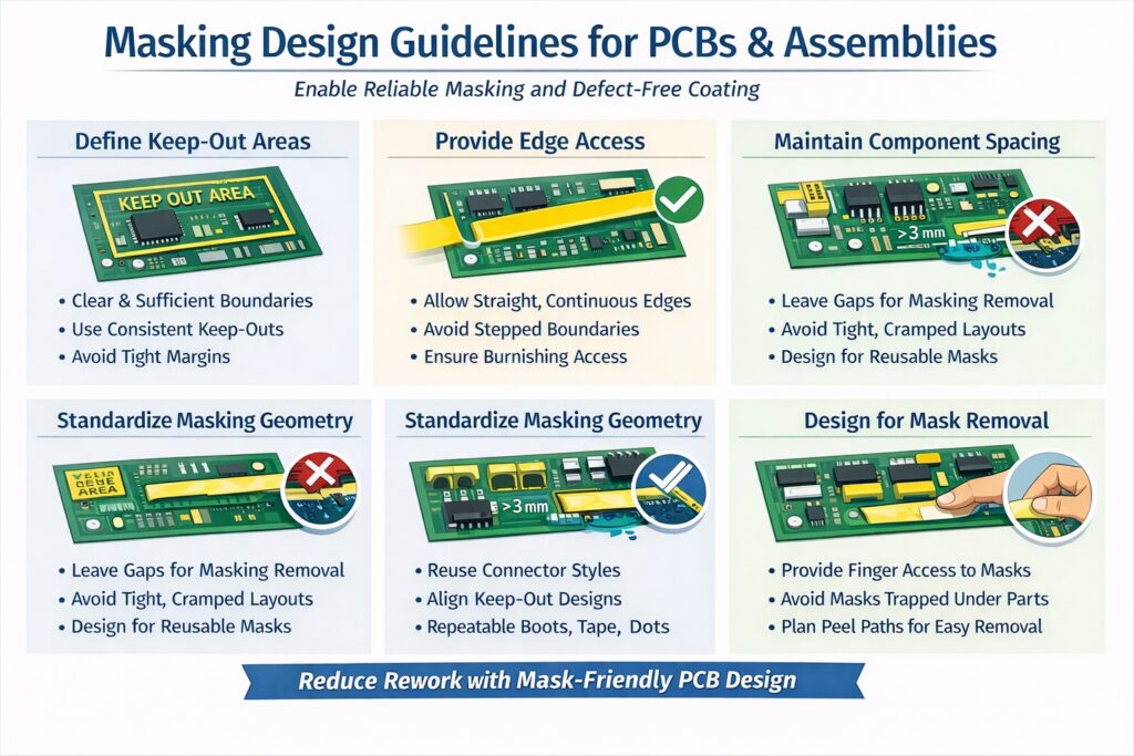
Keep-out areas must be clearly defined, physically accessible, and large enough to be masked without forcing compromise. Ambiguous or undersized keep-outs are a primary cause of masking-related defects.
Best-practice keep-out rules
- Define keep-outs explicitly in drawings and documentation — do not rely on tribal knowledge.
- Allow sufficient boundary width for tape, dots, or shapes to seat and seal properly.
- Avoid tight margins that require masking to overlap onto adjacent components or solder joints.
- Maintain consistency — identical features should have identical keep-out definitions.
Design reality: if a keep-out cannot be masked cleanly using standard materials, it will either be masked inconsistently or not at all.
Edge Access and Boundary Geometry in Conformal Coating Masking
Masking materials require physical access to form a seal. Sharp corners, recessed boundaries, and interrupted edges increase the likelihood of leakage.
Design for edge sealing
- Provide straight, continuous boundaries where possible.
- Avoid stepped or serrated edges that create capillary leakage paths.
- Ensure access for burnishing — operators must be able to press and seal edges.
- Avoid masking boundaries that run directly over solder joints.
If boundaries cannot be simplified, use pre-cut masking shapes for complex geometries to maintain edge definition and repeatability. For irregular connector interfaces or three-dimensional features, reusable masking boots may provide a more stable solution. See our pre-cut masking shape sheets for production-ready solutions.
Component Spacing and Masking Access
Tightly packed assemblies significantly increase masking difficulty. When masking geometry cannot be applied or removed cleanly, it becomes a direct source of coating defects rather than a protective control.
Spacing considerations
- Allow clearance around connectors, test points, and sockets for masking placement and removal.
- Avoid placing critical keep-outs directly between tall components.
- Consider removal forces — masking must be removed without levering against fragile parts.
Where geometry cannot be changed, reusable masking boots may offer a more stable and repeatable masking approach for connector interfaces.
Design Decisions That Increase Defect Risk
Many masking problems originate from design assumptions that do not reflect real production behaviour.
High-risk design choices
- Minimal keep-out margins justified only by layout density.
- Unique keep-outs on every revision, preventing standardised masking.
- Expecting operators to cut complex tape shapes manually.
- Ignoring dwell time and removal access during design.
These decisions force variability into a process that depends on consistency.
For downstream consequences, see Why Masking Causes Most Conformal Coating Defects.
Designing for Masking Standardisation
The most reliable coating lines are built around standard masking sets, not ad-hoc solutions.
Standardisation principles
- Reuse the same connector footprints where possible.
- Align keep-outs across product families.
- Design repeatable features for dots, shapes, or boots.
- Document approved masking strategies per assembly.
Standardisation reduces training time, inspection burden, and defect variability — especially in high-mix environments.
Designing for Clean Mask Removal
Masking design must also consider how the mask will be removed. Poor access or fragile surroundings increase the risk of damage and residue.
- Provide finger or tool access for removal.
- Avoid trapping masks under components.
- Prevent long peel paths that cross sensitive features.
For removal and inspection guidance, see Masking Removal & Verification After Coating.
Design, Process, and Training Alignment
Masking reliability improves dramatically when design, process engineering, and operator training are aligned.
- Design teams understand masking limitations.
- Process engineers define approved masking strategies.
- Operators apply consistent, trained methods.
This alignment prevents defects at source rather than correcting them after coating.
For practical training support, see Conformal Coating Training.
Related Masking Guidance
Why Choose SCH Services?
Partnering with SCH Services means designing for manufacturability from the outset — ensuring masking, coating, and inspection all work together as a controlled system.
- ✔ Design-for-process expertise – bridging PCB design and coating reality
- ✔ Masking strategy development – aligned to real production constraints
- ✔ Defect reduction focus – eliminate issues at design stage, not after coating
- ✔ End-to-end support – from design guidance through to coating and inspection
📞 Call: +44 (0)1226 249019 | ✉ Email: sales@schservices.com | 💬 Contact Us ›
