
Edge Coverage & Drain Paths
Meniscus control and pooling avoidance in conformal coating
Edge coverage and drain paths in conformal coating design directly influence how coatings build on sharp edges, run off vertical surfaces, and collect in local low spots. By planning where the meniscus forms, and giving the liquid a controlled escape route, designers can dramatically reduce pooling, bubbles and thin spots, especially on safety-critical circuits.
1. Why edge coverage & drain paths matter
Liquid conformal coatings behave like any other fluid: gravity, surface tension and wetting drive where the coating ends up after application. If layouts ignore this, the result can be:
- Heavy pooling in cup geometries and low areas.
- Thin edge coverage or exposed sharp corners on tracks and terminations.
- Bridging and whiskers between adjacent leads and pads.
- Air bubbles and voids trapped behind tall parts and walls.
Good drain path design aims to:
- Control where the meniscus stops on edges and walls.
- Give excess coating a clean path to run off, not back onto critical spacing.
- Limit the risk of re-entrant pockets that trap liquid and solvent.
Note: Parylene is a vapour-phase coating, so pooling is not a design driver in the same way, but sharp edges, shadowing and venting still matter for uniform coverage.
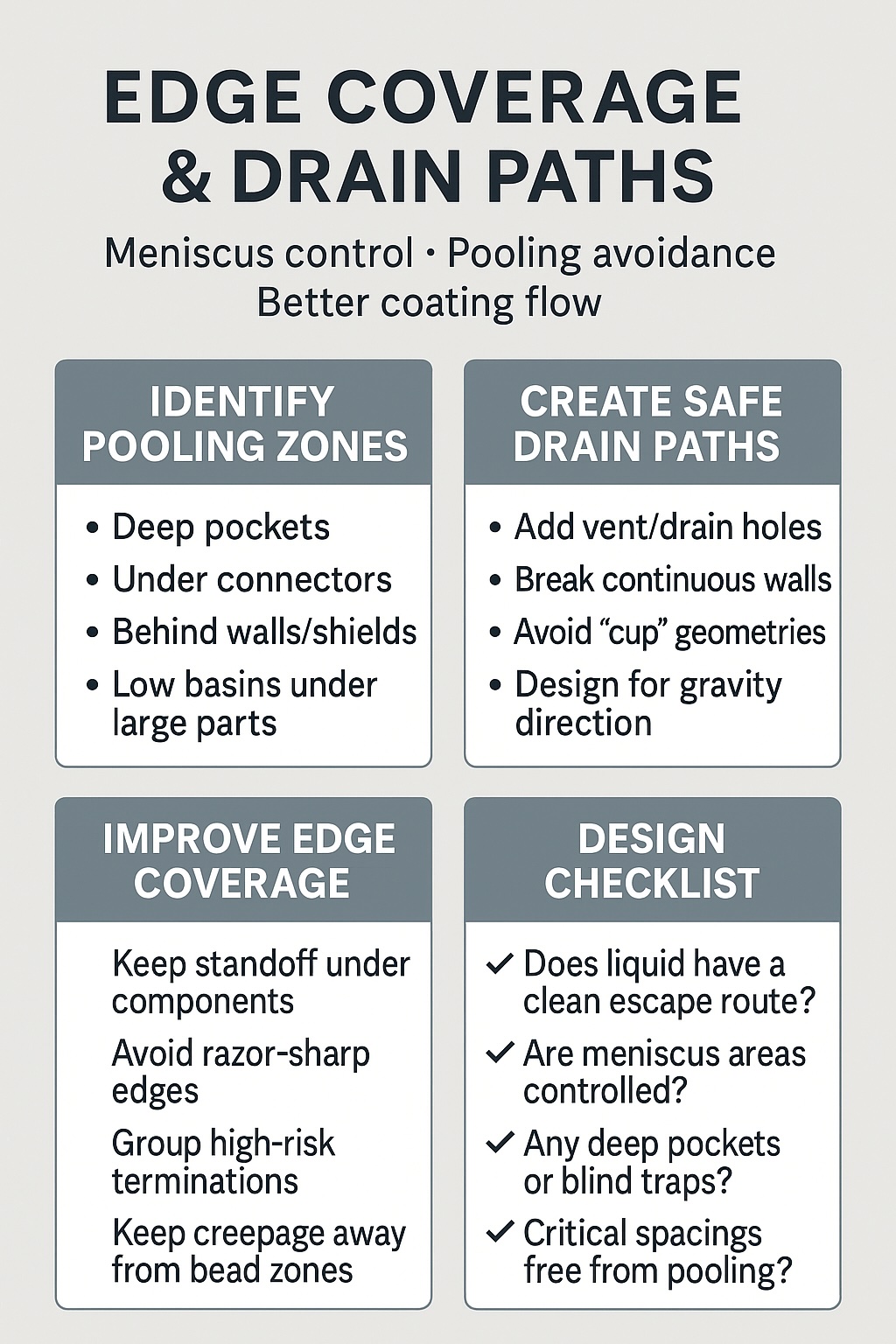
2. Typical pooling and edge-risk areas
When reviewing layouts for edge coverage and drain paths, pay special attention to:
- Board edges and panel tabs – coating can build into thick beads at the perimeter and then drip.
- Vertical walls and shields – create strong menisci and behind-the-wall shadowed zones.
- Connector housings and headers – pockets underneath or between pins can trap liquid.
- Large through-hole pins and cans – meniscus forms around leads; poor spacing can cause bridging.
- Deep pockets and boxed areas – any U-shaped geometry with only one open side is a pooling risk.
- Low areas under large components – liquid runs underneath and can take much longer to dry.
During design reviews, mark these features on the drawing and decide whether you need keep-outs, drain slots, extra vent holes or modified component choices.
3. Designing safer drain paths
A drain path is simply the route coating takes as it flows off a surface during or after application. Good drain design is about ensuring that path is predictable and harmless.
- Give liquid somewhere safe to go
Provide open escape paths at the bottom of deep pockets, not just at the top. If the only exit is high, the pocket will fill and pool. - Use slots and holes rather than blind pockets
Break up flat bowl areas under connectors, shields or housings with slots or vent/drain holes so coating can pass through. - Break long dams and walls
Continuous walls act as dams. Introduce small gaps or staggered sections so coating can drain instead of building into a bead. - Consider process orientation
Ask the coater how assemblies will be fixtured and drained. Design drain paths in the direction of gravity for the planned orientation. - Avoid cup geometries around critical spacings
If safety-critical creepage distances run through recesses or pockets, introduce keep-outs or modify the mechanical design so they are not at the bottom of a bowl.
4. Controlling the meniscus on edges and terminations
The meniscus is the curved boundary where the coating stops. On PCB edges, lead exits and terminations, the meniscus determines whether you get a smooth fillet or a sharp step and thin corner.
Design-side actions to improve meniscus behaviour:
- Maintain sensible standoffs under connectors, shields and large parts so coating can reach and drain rather than bridging.
- Avoid razor-sharp mechanical edges where possible – tiny chamfers or fillets can help coating wrap the corner more evenly.
- Keep critical spacings away from heavy beads – do not place minimum creepage distances at the exact point where a bead will form.
- Group high-risk terminations where masking or controlled flow is easier, rather than scattering them across the board.
Process also matters, including viscosity, application speed and temperature, but robust layouts simplify tuning and make edge coverage more repeatable from batch to batch.
5. Minimising pooling and thickness extremes
Pooling leads to long drying times, solvent entrapment and local stress. To keep thickness in a safe window:
- Flatten extreme level changes where possible; avoid deep pits next to tall towers.
- Use cut-outs under very large components so coating can flow through rather than collecting in one zone.
- Keep test points and connectors out of low basins – raise them or move them to higher, better-drained areas.
- Agree target film thickness with your coater early, so layouts can support the required build without over-pooling.
- Flag known risk zones on the drawing for extra inspection, masking or a different application technique, such as robotic selective spray versus full dip.
6. Edge coverage & drain path design checklist
Use this quick checklist during design and DFM reviews:
- ✅ Have we identified all deep pockets, walls and low basins where coating may pool?
- ✅ Do those features have clear vent and drain paths in the direction of gravity?
- ✅ Are critical creepage and clearance distances kept away from expected beads and build-up zones?
- ✅ Have we allowed standoff under large components and connectors so coating can reach and drain?
- ✅ Are any sharp metal edges chamfered or rounded where possible to support better edge coverage?
- ✅ Have known risk areas been marked on the drawing for masking, special application or extra inspection?
Why Choose SCH Services?
Edge coverage problems are usually created by geometry, not just by coating settings. SCH Services helps customers review meniscus behaviour, pooling risk, drain paths and layout practicality so coatings can flow, drain and cure more consistently on real assemblies.
- 💧 Fluid-Behaviour Design Input – Practical guidance on pooling risk, drain paths, edge beads and geometry-driven coating issues.
- 🛠️ Process-Aware Layout Support – Advice on board features, component placement and application constraints for more predictable film build.
- 🔍 Inspection & Risk Reduction – Help identifying areas likely to trap liquid, dry slowly or create thickness extremes in production.
- 📈 More Repeatable Results – Recommendations aimed at fewer pooling defects, cleaner drain behaviour and better coating consistency.
- 🌍 Integrated Technical Capability – Consultancy, coating services, support equipment and training from one specialist partner.
📞 Call: +44 (0)1226 249019 | ✉ Email: sales@schservices.com | 💬 Contact Us ›
